mcandmar
New member
Choke load vs Constant Current Source:
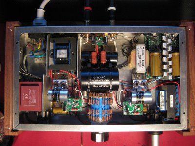
Somebody raised a question recently on the sonic differences between the Hammond 156C choke load and the PJCCS plate load in a stock Quickie. It sparked my curiosity so i took it a step further and implemented a Cascode Current Source as used in a number of Bottlehead amps, but configured for 4.25ma.
The first obstacle was the need of a higher B+ voltage for the CCS, using a bench supply i found 85v was the absolute minimum required, and moving up to 90v, 95v, 100v, 105v showed little to no advantage. The reasoning behind trying these voltages lies with the available 7pin gas voltage regulators. The basic options were,
75C1/0A3 75v 5-40ma
SG16P 80v 5-30ma
85A2 85v 1-10ma
90C1 90v 1-40ma
SG15P-2 102v 5-30ma
SG2P 104v 5-40ma
108C1/OB2 108v 5-30ma
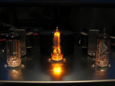
The 85A2 is limited to 10ma which ruled it out as the total load was just over its limit. All the regulators under 100v glow a bright warm orange colour, and all the regulators over 100v glow with a purple/violet hue. They also have a slightly larger bottle, so purely for cosmetic reasons i opted for the 90C1 8)
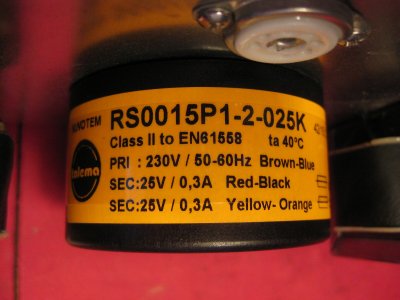
The second obstacle was the raw rectified voltage from the mains transformer was below the ignition voltage of these regulator tubes so i switched the mains transformer from the dual 18v secondary to the next model up in the Talema range (RS0015P1-2-025K) which is identical in physical size, but with two 25v secondary’s. This now allows me to run everything up to the 108C1.
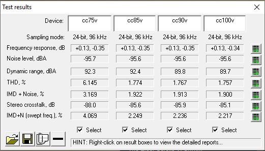
Sonic differences. Frustratingly i spent a day trying to get RMAA to work properly after upgrading my computer to Windows 10 and lost the battle. Therefore any comparisons will have to be purely subjective. The overall difference is a lot smaller than i expected. What i noticed initially was a leaner sounding low end, but with time i have come to the conclusion it is just more controlled and less bloated, which may or may not be a good thing depending on your setup. Mids and highs are so similar it is really splitting hairs trying to differentiate them. It is fair to say the overall presentation just seems a tad cleaner and tighter with the CCS loads, which is probably to be expected. As to which i prefer, i don’t really have a preference as of yet. There seems to be pros and cons for both solutions, technically the CCS will perform better, but subjectively some people may prefer the sound of the choke loads. How is that for an utterly useless conclusion?
Somebody raised a question recently on the sonic differences between the Hammond 156C choke load and the PJCCS plate load in a stock Quickie. It sparked my curiosity so i took it a step further and implemented a Cascode Current Source as used in a number of Bottlehead amps, but configured for 4.25ma.
The first obstacle was the need of a higher B+ voltage for the CCS, using a bench supply i found 85v was the absolute minimum required, and moving up to 90v, 95v, 100v, 105v showed little to no advantage. The reasoning behind trying these voltages lies with the available 7pin gas voltage regulators. The basic options were,
75C1/0A3 75v 5-40ma
SG16P 80v 5-30ma
85A2 85v 1-10ma
90C1 90v 1-40ma
SG15P-2 102v 5-30ma
SG2P 104v 5-40ma
108C1/OB2 108v 5-30ma
The 85A2 is limited to 10ma which ruled it out as the total load was just over its limit. All the regulators under 100v glow a bright warm orange colour, and all the regulators over 100v glow with a purple/violet hue. They also have a slightly larger bottle, so purely for cosmetic reasons i opted for the 90C1 8)
The second obstacle was the raw rectified voltage from the mains transformer was below the ignition voltage of these regulator tubes so i switched the mains transformer from the dual 18v secondary to the next model up in the Talema range (RS0015P1-2-025K) which is identical in physical size, but with two 25v secondary’s. This now allows me to run everything up to the 108C1.
Sonic differences. Frustratingly i spent a day trying to get RMAA to work properly after upgrading my computer to Windows 10 and lost the battle. Therefore any comparisons will have to be purely subjective. The overall difference is a lot smaller than i expected. What i noticed initially was a leaner sounding low end, but with time i have come to the conclusion it is just more controlled and less bloated, which may or may not be a good thing depending on your setup. Mids and highs are so similar it is really splitting hairs trying to differentiate them. It is fair to say the overall presentation just seems a tad cleaner and tighter with the CCS loads, which is probably to be expected. As to which i prefer, i don’t really have a preference as of yet. There seems to be pros and cons for both solutions, technically the CCS will perform better, but subjectively some people may prefer the sound of the choke loads. How is that for an utterly useless conclusion?
")