mcandmar
New member
First off I want to say a big thank you to PB and PJ for their help with this, you guys have been immensely helpful to me as I put this together, so thank you!
For anyone who wants to build a Quickie headphone amp i recommend you start by reading this thread in its entirety first http://bottlehead.com/smf/index.php/topic,2.0.html
To better optimize the Quickie for headphone use the circuit changes as suggested by PJ are two 150H Hammond 156C plate chokes to replace the stock 4.02k resistors, 2k cathode resistors to replace the stock 1.07k's, 5.6uf output caps to replace the stock 2.2uf, and the two Speco T7010 output transformers, preferably the newer small versions. I opted to use the brown (10W) output tap of the Specos for use with Grado 32ohm cans as I found it sounded the best that way, but I recommend you experiment for yourself and find the optimal taps.
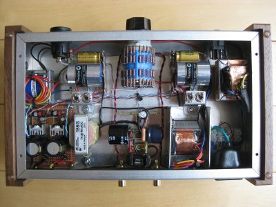
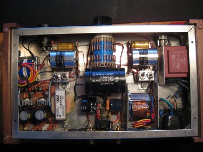
HV Supply: Currently I'm running a dual tap 18v toroid transformer tied together in series and fed through the CLCRC power supply presenting ~40vdc to the plates at idle, or the equivalent of terminals 2 & 7 on the stock Quickie. Rectification is handled by four Murata 820G diodes, I won a bunch of them on ebay super cheap, they are ultrafast and have a small forward drop of ~.8v. Smoothing is done by a 470uf cap, Hammond 155G 7H choke, 150uf cap, 3k resistor, 47uf cap, then into the two 150H plate chokes. Probably complete overkill but it made my target of ~40v and when modeled in PSUDII had 1.5uv of ripple before the two 150H plate chokes so it should be super quite. I found the 155G choke in the Parts Connexion bargain bin half price so figured I may as well use it. Note all the caps are Panasonics rated for 100v as although the nominal voltage is 40-43volts without load that voltage can jump up to 60-63 volts (i.e. without the filament heaters running). There is also a 150k bleeder resistor across the circuit that takes forever to discharge, i should really make that a higher value.
Filament Supplies: They key here was to have two fully independent supplies that are floating. I.e. the ground lines should not be connected to each other, the chassis GND, or the HV supply as when in circuit the negative side gets connected the + side of the cathode bypass capacitor and floats ~4v up from the HV ground. In testing it seemed possible to use a single tap transformer and feed two rectifier sections but in the final design I opted for a dual tap 4.5vac transformer to fully isolate the supplies from each other.
Each tap of the transformer is feeding a bridge rectifier comprised of 1N5818 diodes (~.5v drop), then into a 10000uf 10v cap. Probably overkill again but i happened to have two of them in my parts box. The two regulators are LM317's configured for a 1.4v output. I went full on belt and braces with the datasheet and added a .1uf ceramic cap across the input side, 1uf WIMA poly cap on the output, and a 10uf lytic across the Cadj which serves to prevent any voltage oscillation. Finally two more diodes were added, one bypassing the 10uf Cadj cap and another bypassing the LM317 itself for short circuit protection. The two adjustment resistors are 499/75ohm giving a theoretical output of 1.438v, again they were the values I had to hand. The final output cap is a 220uf 4v Blackgate, another find on the Parts Connexion website I couldn't pass up as I had never actually seen one of those mythical Blackgates in person, and theoretically they are in the audio path so that was my justification. Just note if the adjust resistor circuit should fail the LM317 will default to 5v output and those caps will probably try and turn inside out. The circuit as about as quite as I could make it using my scope to check different component values and positions. It's not battery quite, but very close to it.
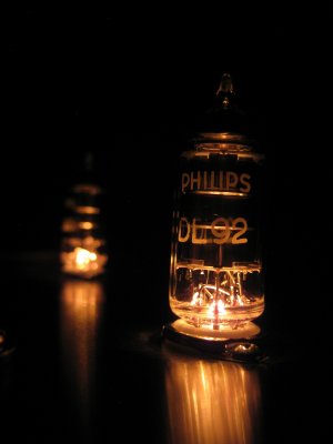
Those eagle eyes among you may be wondering what the other two blue wires coming out of the filament supply board are for, those are connected to two "grain of wheat" light bulbs inserted into the middle of each tube socket. Since these tubes are cold blooded and don't glow I figured lighting them up would A) look cool, and B) serve as a power on indicator. The bulbs themselves are rated for 12v and commonly used on model railways, in this circuit they are being fed ~6v so they have a nice subdued glow to them.
Bling bits: The two 5.6uf Clarity ESA output caps where chosen due to their surprisingly low price for a polypropylene cap, and being 250v items were physically small too. The cathode bypass caps are Nichicon Gold tune 1000uf 16v items I had purchased for another project that didn't physically fit, so again they were floating around my parts box. I did have to laugh after soldering them in and sitting back to see two gold/silver caps shining back at me, honestly the bling factor was unintentional")
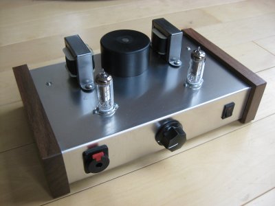
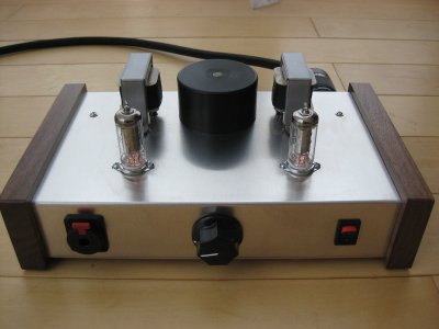
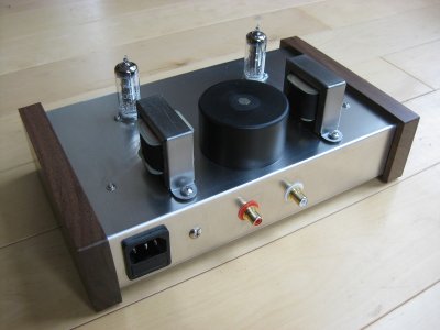
Enclosure: This was a homage to you Bottlehead guys as the pictures i have seen of the original Quickie prototype looked like it was built on a Hammond chassis. This is the deluxe version with wooden end plates (Hammond 444-16CWW). I tried to think if Bottlehead made a Quickie headphone amp what would it look like. Obviously a bit like a S.E.X. amp with two chokes on top either side of the main transformer on an alloy plate with a wood base. I even copied your designs with fiber washers to mount the chokes with a dedicated earth bus. I gave the chokes a brushed metal finish with 400grit sandpaper, clear coat, and then used Docs tip of wrapping the choke bobbins with leather strips. Overall i like to think its got that Bottlehead vibe to it.
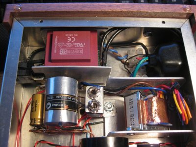
The biggest hurdle I had to overcome was mains hum. In my original layout the filament transformer was located directly under a plate choke, a nice symmetrical design with the two output transformers tucked away in the front of the chassis. The problem was the choke picked up the 50hz hum from the filament transformer, and as I quickly learnt those 150H chokes are super sensitive to magnetic fields. Locating the transformer in the front corner of the chassis in place of the output transformer worked a treat, however the output transformer then started interacting with the plate choke giving me another hum to deal with. The solution was the rather unusual off axis mounting position, a mounting bracket/shield, and a few wraps of copper tape around the transformers to lower the noise enough to be a distant hum with my most sensitive headphones. Its not perfect, but the best I can do for now.
Had I to do it again I would use a slightly larger chassis to move the transformer further away, or find a shielded transformer that radiates less. In an ideal world I would find a suitable transformer with both HV and Filament windings. I haven't ruled out the possibility of using a bigger transformer to run the tubes closer to their maximum rated voltages of 90v.
Never mind all that technical mumbo jumbo, so how does it sound? Just like a quickie, or one that's gone through puberty and gained a deeper voice with some authority. Ok it's not the most powerful amp in the world but with my super sensitive Grados I use ~3/4 volume for normal listening levels and it delivers a crystal clear and precise sound while remaining incredibly neutral. Its still got that Quickie magic to it, but with a surprising depth to its bass I don't remember the quickie ever having to go along with that high end extension. No exaggeration I can listen to this amp for hours and not feel like I am missing out by not using my S.E.X. amp and that's saying something. I love this thing, and to coin Docs phrase, there may be a little bit of proud papa syndrome at play here, but I am astounded at how nice this sounds. I only wish I could hand it to you guys and say here listen to this and see what your reaction is, maybe it sounds crappy and I just cant hear it. Either way i can't take all the credit, it's just another great Bottlehead product in a new enclosure so thanks again guys for designing it and for helping me customize it.
I've attached the schematics for the power supply parts so you can all laugh and point fingers at my mistakes
For anyone who wants to build a Quickie headphone amp i recommend you start by reading this thread in its entirety first http://bottlehead.com/smf/index.php/topic,2.0.html
To better optimize the Quickie for headphone use the circuit changes as suggested by PJ are two 150H Hammond 156C plate chokes to replace the stock 4.02k resistors, 2k cathode resistors to replace the stock 1.07k's, 5.6uf output caps to replace the stock 2.2uf, and the two Speco T7010 output transformers, preferably the newer small versions. I opted to use the brown (10W) output tap of the Specos for use with Grado 32ohm cans as I found it sounded the best that way, but I recommend you experiment for yourself and find the optimal taps.
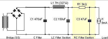
HV Supply: Currently I'm running a dual tap 18v toroid transformer tied together in series and fed through the CLCRC power supply presenting ~40vdc to the plates at idle, or the equivalent of terminals 2 & 7 on the stock Quickie. Rectification is handled by four Murata 820G diodes, I won a bunch of them on ebay super cheap, they are ultrafast and have a small forward drop of ~.8v. Smoothing is done by a 470uf cap, Hammond 155G 7H choke, 150uf cap, 3k resistor, 47uf cap, then into the two 150H plate chokes. Probably complete overkill but it made my target of ~40v and when modeled in PSUDII had 1.5uv of ripple before the two 150H plate chokes so it should be super quite. I found the 155G choke in the Parts Connexion bargain bin half price so figured I may as well use it. Note all the caps are Panasonics rated for 100v as although the nominal voltage is 40-43volts without load that voltage can jump up to 60-63 volts (i.e. without the filament heaters running). There is also a 150k bleeder resistor across the circuit that takes forever to discharge, i should really make that a higher value.
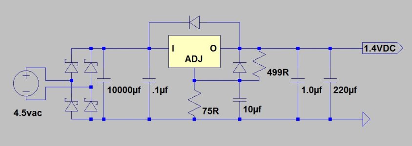
Filament Supplies: They key here was to have two fully independent supplies that are floating. I.e. the ground lines should not be connected to each other, the chassis GND, or the HV supply as when in circuit the negative side gets connected the + side of the cathode bypass capacitor and floats ~4v up from the HV ground. In testing it seemed possible to use a single tap transformer and feed two rectifier sections but in the final design I opted for a dual tap 4.5vac transformer to fully isolate the supplies from each other.
Each tap of the transformer is feeding a bridge rectifier comprised of 1N5818 diodes (~.5v drop), then into a 10000uf 10v cap. Probably overkill again but i happened to have two of them in my parts box. The two regulators are LM317's configured for a 1.4v output. I went full on belt and braces with the datasheet and added a .1uf ceramic cap across the input side, 1uf WIMA poly cap on the output, and a 10uf lytic across the Cadj which serves to prevent any voltage oscillation. Finally two more diodes were added, one bypassing the 10uf Cadj cap and another bypassing the LM317 itself for short circuit protection. The two adjustment resistors are 499/75ohm giving a theoretical output of 1.438v, again they were the values I had to hand. The final output cap is a 220uf 4v Blackgate, another find on the Parts Connexion website I couldn't pass up as I had never actually seen one of those mythical Blackgates in person, and theoretically they are in the audio path so that was my justification. Just note if the adjust resistor circuit should fail the LM317 will default to 5v output and those caps will probably try and turn inside out. The circuit as about as quite as I could make it using my scope to check different component values and positions. It's not battery quite, but very close to it.
Those eagle eyes among you may be wondering what the other two blue wires coming out of the filament supply board are for, those are connected to two "grain of wheat" light bulbs inserted into the middle of each tube socket. Since these tubes are cold blooded and don't glow I figured lighting them up would A) look cool, and B) serve as a power on indicator. The bulbs themselves are rated for 12v and commonly used on model railways, in this circuit they are being fed ~6v so they have a nice subdued glow to them.
Bling bits: The two 5.6uf Clarity ESA output caps where chosen due to their surprisingly low price for a polypropylene cap, and being 250v items were physically small too. The cathode bypass caps are Nichicon Gold tune 1000uf 16v items I had purchased for another project that didn't physically fit, so again they were floating around my parts box. I did have to laugh after soldering them in and sitting back to see two gold/silver caps shining back at me, honestly the bling factor was unintentional
Enclosure: This was a homage to you Bottlehead guys as the pictures i have seen of the original Quickie prototype looked like it was built on a Hammond chassis. This is the deluxe version with wooden end plates (Hammond 444-16CWW). I tried to think if Bottlehead made a Quickie headphone amp what would it look like. Obviously a bit like a S.E.X. amp with two chokes on top either side of the main transformer on an alloy plate with a wood base. I even copied your designs with fiber washers to mount the chokes with a dedicated earth bus. I gave the chokes a brushed metal finish with 400grit sandpaper, clear coat, and then used Docs tip of wrapping the choke bobbins with leather strips. Overall i like to think its got that Bottlehead vibe to it.
The biggest hurdle I had to overcome was mains hum. In my original layout the filament transformer was located directly under a plate choke, a nice symmetrical design with the two output transformers tucked away in the front of the chassis. The problem was the choke picked up the 50hz hum from the filament transformer, and as I quickly learnt those 150H chokes are super sensitive to magnetic fields. Locating the transformer in the front corner of the chassis in place of the output transformer worked a treat, however the output transformer then started interacting with the plate choke giving me another hum to deal with. The solution was the rather unusual off axis mounting position, a mounting bracket/shield, and a few wraps of copper tape around the transformers to lower the noise enough to be a distant hum with my most sensitive headphones. Its not perfect, but the best I can do for now.
Had I to do it again I would use a slightly larger chassis to move the transformer further away, or find a shielded transformer that radiates less. In an ideal world I would find a suitable transformer with both HV and Filament windings. I haven't ruled out the possibility of using a bigger transformer to run the tubes closer to their maximum rated voltages of 90v.
Never mind all that technical mumbo jumbo, so how does it sound? Just like a quickie, or one that's gone through puberty and gained a deeper voice with some authority. Ok it's not the most powerful amp in the world but with my super sensitive Grados I use ~3/4 volume for normal listening levels and it delivers a crystal clear and precise sound while remaining incredibly neutral. Its still got that Quickie magic to it, but with a surprising depth to its bass I don't remember the quickie ever having to go along with that high end extension. No exaggeration I can listen to this amp for hours and not feel like I am missing out by not using my S.E.X. amp and that's saying something. I love this thing, and to coin Docs phrase, there may be a little bit of proud papa syndrome at play here, but I am astounded at how nice this sounds. I only wish I could hand it to you guys and say here listen to this and see what your reaction is, maybe it sounds crappy and I just cant hear it. Either way i can't take all the credit, it's just another great Bottlehead product in a new enclosure so thanks again guys for designing it and for helping me customize it.
I've attached the schematics for the power supply parts so you can all laugh and point fingers at my mistakes