Noise with Computers, USB DACs, and Powerline Ethernet Kits

Paul Birkeland

Moderator
Staff member
For those who can hear their computer working away through their Crack or who are using a powerline ethernet kit and hear lots of clicking and static, a ground breaker installed in place of the buss wire between the chassis and the ground tab of the IEC power entry module will very likely solve this issue.  I recommend using a diode that's rated for at least 2A, and the voltage isn't particularly important.  Part number STTH2R06 looks to be a solid choice.  I do not recommend using a Schottky diode here. 

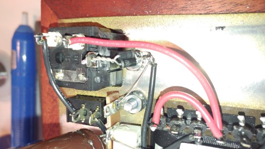
I've attached a photo of how this is retrofitted into a Crack. 
 

Attachments

  • 20190620_120630.jpg
    20190620_120630.jpg
    5.9 MB · Views: 1,839
Would this work on any of the other kits? I have a S.E.X. that has this issue. I use an ifi USB filter that works, but it would be nice to bypass that.
 
This is very cool.


@PB: can you explain how it works?


It doesn't make sense to me. Two ideal diodes paralleled with reversed polarities would do nothing, right?  All current/voltage would pass unimpeded in either direction. So I figure it must work ONLY BECAUSE real world diodes are non-ideal.


I've seen ground loop breakers that employ a diode bridge with a resistor and cap to greatly reduce ground loops - but you're using only the diode bridge. Does the tiny amount of resistance and capacitance of the diodes do the trick?  Or is something else at work here?


many thanks,


Derek
 
denti alligator said:
Would this work on any of the other kits? I have a S.E.X. that has this issue. I use an ifi USB filter that works, but it would be nice to bypass that.
Give it a shot and let us know!


Deke609 said:
@PB: can you explain how it works?
It separates the safety ground by the voltage drop of one diode (in either direction).

Deke609 said:
All current/voltage would pass unimpeded in either direction. So I figure it must work ONLY BECAUSE real world diodes are non-ideal.
Yes, a perfect diode wouldn't allow this arrangement to work.
 
A little more specifically, if you have a small AC voltage, say 100mV, the diodes present a pretty large impedance and this is what's broken.  If you have more than about 0.7V of anything AC or DC, then the diodes will start to short that out.
 
Deke609 said:
@PB: why not a Schottky?
You want the forward voltage drop to be significantly higher than the magnitude of the noise you're dealing with.  The low forward voltage drop of a Schottky diode in this instance is a bit of a disadvantage.
 
I’m thinking about giving this a shot. Is there any amp in the lineup where this would be unsafe or a bad idea? I assume not but don’t want to make a costly mistake.
 
I don't see issues doing this with any of our products.  I do also plan to test whether a UF4007 can throw a 20A breaker and survive, as this could also be a suitable part to use.
 
I picked up a dozen or so and will probably add them to every kit next time any of them are on the bench for one reason or another.

Any downsides to doing it besides the minimal effort and cost?
 
Installed this last night and all seems to be well so far. One caveat for folks wanting to try this in the future - the ground tab opening gets pretty congested with the two buss wires and the twisted leads of the diodes. Prepare for some cussing and finagling. It definitely helped to clear all the extant solder out of the hole first.
 
Hello,

This is a mod I would like to try as I have always had a bit of noise from my PC audio.

That said, I am essentially a beginner with this stuff. I built a Crack + Speedball and had no issues. However, to mod my crack I'm a bit lost. I have an original Crack and not 1.1. Your picture looks a bit different than mine does. Mine looks exactly like in this picture - https://i.imgur.com/ZknbokI.png . This is pulled from the original crack manual, as my Crack is on currently and hot.. haha. But, it looks the same.

How would I go about performing this mod? Also, do you need 2 x STTH2R06 diodes?

Sorry for my ignorance and thanks!

HMF
 
There is no difference in installing the diodes in the Crack 1.0 vs. 1.1.  Both amps have a piece of buss wire from the IEC power entry ground to the chassis solder lug.  This is cut out, then the diodes are soldered in its place.
 
Paul Birkeland said:
There is no difference in installing the diodes in the Crack 1.0 vs. 1.1.  Both amps have a piece of buss wire from the IEC power entry ground to the chassis solder lug.  This is cut out, then the diodes are soldered in its place.

Ahhh. So you leave the buss wire going from the chassis soler lug -> terminal 16L, and replace the buss wire going from the chassis solder lug to the IEC power entry ground with the 2 diodes?

In that case.. easy peasy.

I was confused about the black wire in the original posts attached pciture running into the chassis solder lug, as I don't have that present on my Crack. Wanted to make sure I wasn't missing something.

Thanks for the reply.
 
Back
Top