MrPotatoSalad
New member
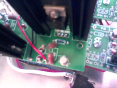
Same LEDs still lit. Voltage B2/B5: 71VCaucasian Blackplate said:There's a red jumper that goes from B+ to B+ on the big Speedball board. Yank that, then remeasure B2/B5.
Same LEDs still lit. Voltage B2/B5: 71VCaucasian Blackplate said:There's a red jumper that goes from B+ to B+ on the big Speedball board. Yank that, then remeasure B2/B5.
That's the problem area.MrPotatoSalad said:Top O out:
1:68
2:70
4:70
5:21
LEDs same
That side is good.MrPotatoSalad said:Bottom O out:
1:83
2:204
4:204
5:78
All LEDs on except the bottom main board LEDs are out and top LEDs are bright.
The LED's on the small PC boards should've been lit up pretty brightly with the 6080 out. The LED's on the socket couldn't light unless this was the case.MrPotatoSalad said:Also, both LEDs on the 12AU7 socket went on with the 6080 out. All board LEDs were out.
You are correct, they just weren't noticeable with my lights.Caucasian Blackplate said:The LED's on the small PC boards should've been lit up pretty brightly with the 6080 out. The LED's on the socket couldn't light unless this was the case.
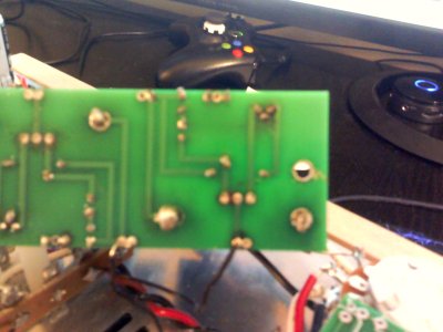
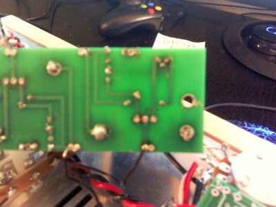
No visible connection or measured connecection with any of the transistor legs. Perhaps the TIP50 or 2N2222 is bad?Caucasian Blackplate said:I would go over that big board with a fine toothed comb. You have one side that is doing what it should, and one side that isn't. The most probable cause at this point is that two legs of a transistor on that side of the big PCB are soldered together.
-PB
We use essential cookies to make this site work, and optional cookies to enhance your experience.