New Crack build.

richmi

New member
Hello all,

I finished building my Crack yesterday. It was a relatively easy build, except for some customization I did that gave me some trouble.

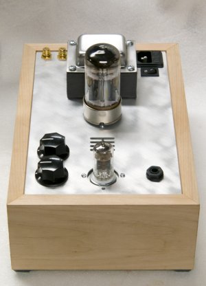
I am hearing impaired, appreciably more so in one ear than the other. So, I needed to have separate volume controls. I did not find any dual concentric potentiometer (which is what I would have preferred: I would not have had to bore a second hole in the chassis plate), so I bought two mono pots.

I also wanted to be able to convert it eventually to 6SN7 for the fun of it and also because I have many of that tube. So, I needed a bigger hole for the octal socket.

Resistance and voltage readings were all within 3%, so I was pretty impressed! Best measurements of all my kits.

Went to bed at 1:30 this morning after listening for 3 1/2 hours. As others remarked, the Crack does not seem to induce fatigue.

I am not a headphone person, but I must admit this thing sounds really good. I realized that my turntable and my Seduction are quieter than I thought. Listening to the HD650 through the Extended Foreplay and the Paramounts is not as quiet (which I did only occasionally as I find it too complicated).

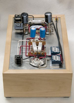
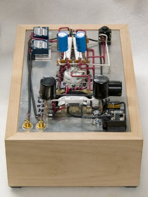
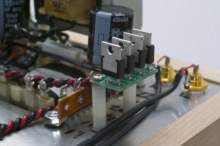
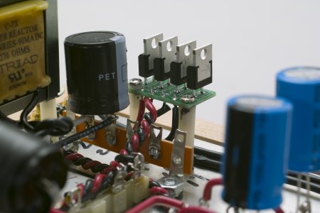
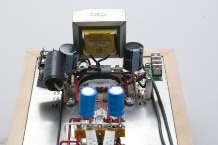
I like looking at other people's photos, so I am posting a few of mines.

Richard
 

Attachments

  • rm_crack_1.jpg
    rm_crack_1.jpg
    1.3 MB · Views: 1,088
  • rm_crack_2.jpg
    rm_crack_2.jpg
    1.8 MB · Views: 1,719
  • rm_crack_3.jpg
    rm_crack_3.jpg
    1.8 MB · Views: 1,125
That really is a superb job Richard.Excellent attention to detail and dressing. You should be most proud of your work.
 
Hello all,

Since last time, I made some changes to my Crack.

I first replaced the last 270 ohm resistor in the power supply with the C-7X choke. Later on, I bypassed the last 220uf capacitor with an Obbligato 2.2uf Gold capacitor. Today, I replaced the stock rectifier bridge diodes with some Cree Schottky diodes. Parts Connexion had a sale on tubes this week, so I ordered the Schottkys along with a pair of tubes I needed.

So far, I have been able to hear all the changes I made, to my great surprise, given that my hearing is defective. I thought they would be way too subtle for me to hear. Overall, better details, better separation of instruments and voices, and today I think I noticed a difference in the way strings sound; I will have to listen more. In any case, I did not lose anything, since I have had those parts for years in a drawer. The only new expense was the diodes.

I read somewhere that PB mentioned that he was concerned with some safety issue with the installation of the Schottky diodes. Has it something to do with the possibility of shorting something with the metal parts or more something to do with shock hazard? Should I cover the diodes with heat shrink? Could there be any problem with where I elected to place them?

I still have two 100uf film capacitors to install, and I had to take that into account in chosing where to put the Schottky. And after that, it is going to be the Speedball.

Any comment or suggestion is appreciated.

Thanks, Richard
 

Attachments

  • rm_crack_4.jpg
    rm_crack_4.jpg
    1.6 MB · Views: 1,216
  • rm_crack_5.jpg
    rm_crack_5.jpg
    1.5 MB · Views: 780
  • rm_crack_6.jpg
    rm_crack_6.jpg
    1.4 MB · Views: 835
I like the little diode bridge PCB, where did you find that?

Personally i would put a bit of heatshrink over each of them as the metal tab is connected to the output side and will have high voltage on them.
 
I found the rectifier PCB at Parts Connexion for $1.95. I intended to make my own board and hard wire it, but at that price, it was not worth it. I wished for more room for the screws. I don't think it is meant to be mounted this way.

I suspected the Schottkys might be "live". I was extra careful when I did the voltage checks after the installation.

Richard
 
richmi said:
I found the rectifier PCB at Parts Connexion for $1.95. I intended to make my own board and hard wire it, but at that price, it was not worth it. I wished for more room for the screws. I don't think it is meant to be mounted this way.

I had a bunch of PCB's made for TO-220 package diodes and found the same, wished i had left more space around the mounting screws. I also mounted them the same way using nylon standoffs so it looks alright to me.  I must pick up some of those as its cheaper than having them made  :)
 
Yeah, the TO-220 package doesn't lend itself to being installed in the Crack without a supporting PC board.  The one that you found is just the ticket!

-PB
 
Richard,

I have received my Schottky diodes and PC board today. Still need to drill holes for mounting, but I am having trouble finding information on what type of drill-bit to use. May I ask what you used for this?

Cheers,
 
Gunter,

The nylon standoffs I have are from Hong Kong, as I could not find any here in my neighbourhood (Canada). They are metric and take M3 screws.

I used a sharp drill bit attached to a Dremel tool to bore the holes in the PCB.

Indeed, there is not much room on this PCB for mounting screws. I do not think they are meant to be mounted this way, but it works.

If you look at my pictures, you will see that I added a nylon washer on the + side, as I did not want the screw to touch the connexion there; the screw sits pretty close.


Grainger,

Parts Connexion has a search function. If you look for "rectifier pcb", you will find the one I used and many others.

Richard
 
Richard,

Thanks for clarifying.

I saw that nylon washer, but I did not realise that the PC board would be this small. There is very little space for the holes, and right now I am contemplating just super-gluing the PC board to the standoffs. I really try and avoid glue for most applications, but I think this will be the cleanest solution.

Cheers,

Gunter
 
Back
Top