EricS
Member
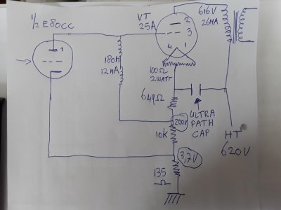
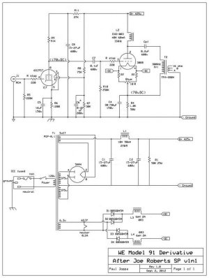
For the past two years, I've been gathering parts for a new tube amp - the Magnequest iron took the longest time to track down and several of you here have contributed - thank you. I have built lots of solid state stuff, but this will be my first tube amp. The design is Paul Joppa's parafeed update to Joe Roberts' Western Electric Model 91 300B that was published in Sound Practices in the Summer 1992 issue. Paul has graciously granted his permission for me to post his design and my thread here. Thank you, Paul!
This build will likely take me several months to complete from here. Since this is my first tube build, I'm likely to need a fair amount of guidance in the form of "hey, dummy - don't do that!" I have read Morgan Jones' "Building Valve Amplifiers" and have tried to incorporate his long list of physical layout guidelines, though I'm sure I have missed several fundamentals.
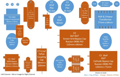
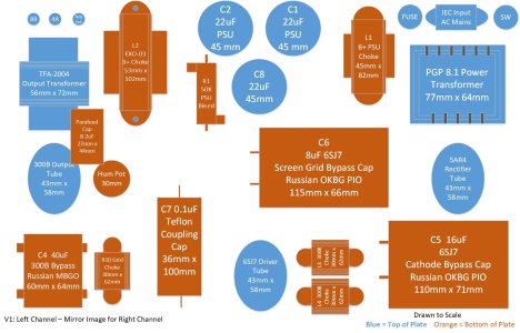
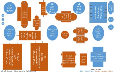
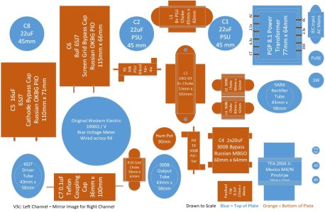
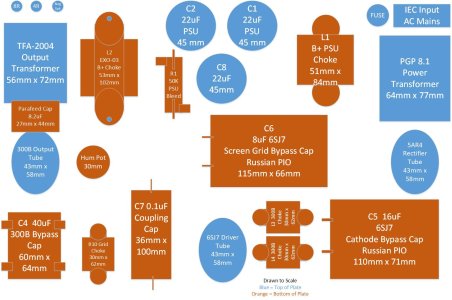
Attached are Paul's schematic (I have added all of the parts values) and my first attempt at a 2-dimensional layout the physical components (quick and dirty Visio drawing - for easy rearranging over time). The overall top plate as of now is 11" x 17" and each of the parts is drawn relatively close to actual scale. The final layout will likely be a little smaller in footprint. The blue components will be mounted on the top of the plate, the orange components will be hidden on the bottom of the plate. I have aimed for both visual appeal (physical symmetry of top-of-plate parts) and what appears (to me, at least) to be a reasonable first pass at an electrical layout.
Here is where I need your help: What have I done wrong? Which parts should not be next to one another? How can I improve the parts layout to improve running wires or preventing unwanted interactions?
My ongoing thanks and appreciation in advance!
This build will likely take me several months to complete from here. Since this is my first tube build, I'm likely to need a fair amount of guidance in the form of "hey, dummy - don't do that!" I have read Morgan Jones' "Building Valve Amplifiers" and have tried to incorporate his long list of physical layout guidelines, though I'm sure I have missed several fundamentals.
Attached are Paul's schematic (I have added all of the parts values) and my first attempt at a 2-dimensional layout the physical components (quick and dirty Visio drawing - for easy rearranging over time). The overall top plate as of now is 11" x 17" and each of the parts is drawn relatively close to actual scale. The final layout will likely be a little smaller in footprint. The blue components will be mounted on the top of the plate, the orange components will be hidden on the bottom of the plate. I have aimed for both visual appeal (physical symmetry of top-of-plate parts) and what appears (to me, at least) to be a reasonable first pass at an electrical layout.
Here is where I need your help: What have I done wrong? Which parts should not be next to one another? How can I improve the parts layout to improve running wires or preventing unwanted interactions?
My ongoing thanks and appreciation in advance!
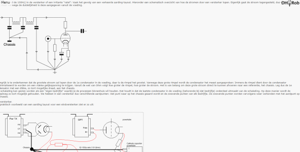
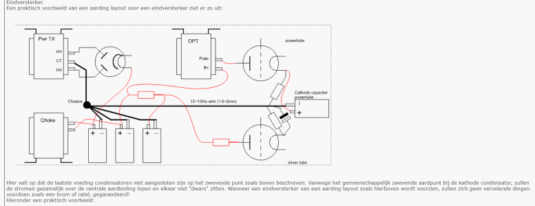
 . It covers all basics on tube amp layout. With every layout i try, i'd reread it several times and combine this with the BH manuals i own. To see what practices i could improve on, even after the breadboard. Searching the internet for completed versions of your amp also helps a lot ime.