You are using an out of date browser. It may not display this or other websites correctly.
You should upgrade or use an alternative browser.
You should upgrade or use an alternative browser.
Modifications to run e80cc/12bh7a/5687 for Crack+Speedball
- Thread starter kscwuzhere
- Start date
guildenstern
New member
Doc B. said:Those switches are way too small. You should upgrade to something like this.

I'm actually thinking of something a little more retro and heavy duty...
Attachments
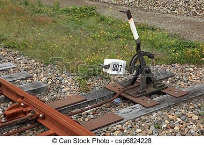
guildenstern said:I'm hoping one of you technically savvy forum members can help. On Head-Fi I bought a modded Crack from a BH forum member -- great build and very enjoyable sound. What I can't get from the builder is a clear explanation about which way the switches should be set for 12AU7 and which way for E80CC. Here are pictures of the resistor switch assembly he devised, taken by the builder of the amp. If you can use these pictures to deduce the proper switch positions for 12AU7 vs E80CC, I would appreciate it. Especially if you can explain in "for dummies" terms (as I readily confess I am). Thanks in advance.
In the speedball circuit there's a series resistor from B+ to the 2N2907 transistor that sets the current flowing through the tube. The stock 12AU7 uses a 238 ohm resistor while the E80CC requires 470 ohms. In the photo you can see that the switch is connecting a 470 ohm resistor in parallel with the resistor on the board (which looks to be 470 ohms). When the switch is open it's set for an E80CC. When the switch is closed, it's set for a 12AU7.
I'm not familiar enough with rocker switches to tell you which position is which (I only know toggle switchs). You can take a DVM and measure the resistance on the switch between the middle and right terminal. 470 ohms = E80CC and 235 ohms = 12AU7.
guildenstern
New member
Maxhawk said:In the speedball circuit there's a series resistor from B+ to the 2N2907 transistor that sets the current flowing through the tube. The stock 12AU7 uses a 238 ohm resistor while the E80CC requires 470 ohms. In the photo you can see that the switch is connecting a 470 ohm resistor in parallel with the resistor on the board (which looks to be 470 ohms). When the switch is open it's set for an E80CC. When the switch is closed, it's set for a 12AU7.
I'm not familiar enough with rocker switches to tell you which position is which (I only know toggle switchs). You can take a DVM and measure the resistance on the switch between the middle and right terminal. 470 ohms = E80CC and 235 ohms = 12AU7.
Thanks very much, Maxhawk. I will dig out the VOM and give it a try. Thanks again.
For those planning on the upgrades described here. A word on 12BH7 as i've found from testing 10+ 12BH7 the optimum is a bit lower then the 140 ohm often advocated. This current trough the tube, still functions fine with 5687/7119/182CC with 3,2V bias.
For the R1 value's -> with E80CC i use 475 ohm, for 12AU7's the 237ohm from standard Crack for 12BH7 (mind the MJE 5731A transistor) I use 113 ohm. With your normal E182CC it sits at 85V with the 8mA of current, with weaker ones this goes over 90V, so beware.
With 12BH7 and E182CC on the same R1 with different bias point's. it's a bit of a balancing act, but this works perfectly.
But there's always more tubes to experiment with.
If i'd wanted to try a more current demanding tube to get in the optimal voltage range -> lower R1 even further? Can i do this?
What's the maximum current that Speedball and the powersupply will handle?
And how do i calculate from R1 value -> current?
R1 = 0.855/current is the formula. You don't have to be perfect on the resistor value, just close. R2 needs to pass about 10% of the current your setting, or 1mA, whichever is more.
So, the power transformer in the Crack can supply a TON! of HV current. The first limiting factor will be those 270 ohm 5W resistors. The current circuit uses about 75mA of current and I wouldn't want to run much more than about 80 before the life of those resistors will drop. If you wanted to run more current, you could swap out the 270R/5W resistor that sits on top of the power transformer with a 300R/10W resistor, then make the other 270R/5W resistor into a 200R/5W resistor. You can reliably run 90mA through a 200R/5W resistor, and the 300R/10W resistor won't get all that toasty.
The other issue is the dissipation of Q2 up front. The MJE5731A is good for about 1W of dissipation, so even at 10mA I wouldn't be too worried about heatsinking it.
Thank you PB. For your detailed explanation.
This sure helps a lot. I'll get my Crack up to 10mA and leave it at that. That's perfect for the tube in mind.
It's the BL63. Not many use it with Crack as it's expensive, takes too much heater current (1.3A!) for the Crack to provide, and this much plate current will cook the transistor you mentioned. And there's no detailed datasheet / curves available, so we have no clue how it'll settle in Crack. This is a true recipe for disaster.
So, that's why i've decided to try it in my Crack") . With A2293 as output pair, there's 1.6A left for the driver and the BL63 became an option. Still it lacked any data.
. With A2293 as output pair, there's 1.6A left for the driver and the BL63 became an option. Still it lacked any data.
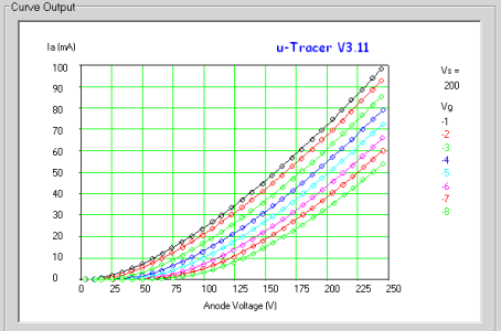
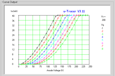
I've added a curve i traced on this tube. You can see why i'm planning on 10mA, it comes right in the suggested plate voltages with -3,2V bias (blue led). This is the same as with E182CC/5687 and can be used with the flick of a switch. I've now tried it at 7.5mA and this turn out to show 55V on the plate with the normal red LED bias.
For those interested in these curves. I've also added E80CC and ECC82 to compare. Do note, the ECC82 doesn't appear to be very healthy.
This sure helps a lot. I'll get my Crack up to 10mA and leave it at that. That's perfect for the tube in mind.
It's the BL63. Not many use it with Crack as it's expensive, takes too much heater current (1.3A!) for the Crack to provide, and this much plate current will cook the transistor you mentioned. And there's no detailed datasheet / curves available, so we have no clue how it'll settle in Crack. This is a true recipe for disaster.
So, that's why i've decided to try it in my Crack
. With A2293 as output pair, there's 1.6A left for the driver and the BL63 became an option. Still it lacked any data. I've added a curve i traced on this tube. You can see why i'm planning on 10mA, it comes right in the suggested plate voltages with -3,2V bias (blue led). This is the same as with E182CC/5687 and can be used with the flick of a switch. I've now tried it at 7.5mA and this turn out to show 55V on the plate with the normal red LED bias.
For those interested in these curves. I've also added E80CC and ECC82 to compare. Do note, the ECC82 doesn't appear to be very healthy.
Attachments
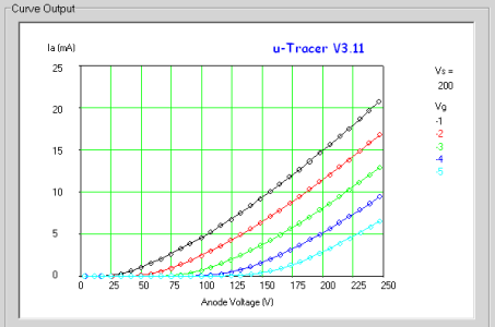
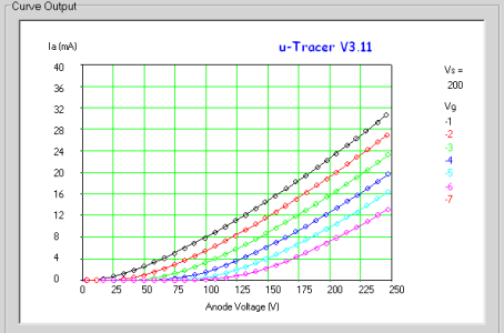
The BL63 traces would be easier to look at if the Y axis only went up to 30mA.
The Crack-a-two-a power transformer would be up to the job of heating that tube as a substitute.
The Crack-a-two-a power transformer would be up to the job of heating that tube as a substitute.
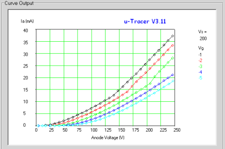
Thank you for the feedback Paul. Did just do another curve with the lower plate current setting on the screen.
The C2A is on my wishlist. When funds permit it's my next BH purchase.
Here's the BL63 curves (wow these look good) with a 6SN7 as comparison.
The C2A is on my wishlist. When funds permit it's my next BH purchase.
Here's the BL63 curves (wow these look good) with a 6SN7 as comparison.
Attachments
C
Clair-de-Loon
Guest
Just wondering if anyone has applied the 12AU7/E80CC/12BH7 switch mod to the newer version of the Speedball that uses the single PCB for the driver. Any hints?
Thanks
Thanks
The circuit and part names are identical, so it should be exactly the same to build this out on the newer Speedball.Clair-de-Loon said:Any hints?
Paul Joppa
Moderator
On the data sheets and in engineering practice, it has long been standard to refer voltages to the cathode - so "plate voltage" technically means the voltage difference between plate and cathode. Similarly, "grid voltage" is the difference between the grid and cathode voltages (which is why it's usually a negative number).
This stems from the days (more than a hundred years ago) when tube circuits usually grounded the cathode, and were powered by three batteries - the A battery heated the filament/cathode, the B battery supplied current to the plate circuit, and the C battery set the grid voltage. That has survived in the use of "B+" for the positive high voltage from the power supply, and in the terms Vb for plate voltage and Vc for the grid voltage. In more academic literature, especially international literature Va for anode voltage, Vg for grid voltage, and Vk for cathode voltage.
Originally the term for voltage was "electromotive force" a.k.a. EMF, and voltages were Eb, Ec, or Ea, Eg, Ek. That's how I learned Ohm's Law, and I am still struggling to remember to write V instead of E. Similarly, current was measured as an "intensity" which is how we came to use I for current.
You may have noticed the substantial opportunities for confusion here! :^)
Paul Joppa said:.....
You may have noticed the substantial opportunities for confusion here! :^)
:-[ ...
What would be called the "plate voltage" of the 6080 would be the difference between plate and cathode voltage on the 6080.Cornysh said:How do you calculate the size of the Va of the 6080? Is it simply a matter of subtracting the Va of the 12AU7 from the total B+?
This is influenced by the plate voltage that appears at the 12AU7, whether you have the Speedball installed, and how potent the particular 6080 is that you're using.
You would start at the plate curves for the 12AU7. Without the Speedball, you would draw a 22.1K load line that starts at about 175V DC, then estimate where that would hit the imaginary 1.57V grid voltage line. Go straight down from there and you get your 12AU7 plate voltage.
With the Speedball, you would draw a horizontal line at 3.2mA and estimate where that would hit the imaginary 1.57V grid voltage line, then go straight down from there to estimate the plate voltage.
The 6080 is a little less conventional, but for DC operating points and load lines it isn't so bad. You can draw a 3K loadline on the 6080 curves that hits 175V. Now on that line, you must find the point where the grid voltage magnitude (make the number positive), plus the 75V you already have, plus the plate voltage on the X axis equals your B+ (175V). Working out some terms, that is the magnitude of grid bias plus the plate voltage equals about 100V. On the curves, this happens at about 70VP and 30V of bias, so just over 30mA of current.
With the Speedball, you draw a horizontal line at 30mA and find the spot where grid bias magnitude and plate voltage add up to about 100V.
If the plate voltage on the 12AU7 moves, then you have to redo the analysis. If your line voltage moves, you have to redo the analysis. I prefer to be happy with estimates!
Yup, that's a decent estimate.
We give bias in voltage. The bias with the Speedball is a variable to solve for. Current is held constant at 30mA. The bias voltage is the conclusion to the work, not the starting point.Cornysh said:Bias = 30
Yes, plate to cathode voltage on the 6080 is about 70V. From the curves, you would get from this that bias voltage is about 30V.Cornysh said:Va - Vk = 70 (determined from curves where plate voltage + bias = 100)
If the grid voltage is 70V and the bias voltage is 30V, then the actual DC voltage at the cathode is 100V.Cornysh said:Vg = 70 (supplied from plate of 12AU7)
Vg - Vk = Bias
70 - Vk = 30
Therefore Vk = 40
Similar threads
- Replies
- 1
- Views
- 2K
- Replies
- 15
- Views
- 4K