You are using an out of date browser. It may not display this or other websites correctly.
You should upgrade or use an alternative browser.
You should upgrade or use an alternative browser.
Modded Crack - add bypass cap, choke and Cree diodes
- Thread starter ALL212
- Start date
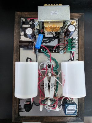
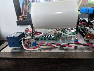
So instead of adding these upgrades to my existing build, I created a new build and incorporated them in. I pretty much followed the original couple of posts, 1uf Clarity Cap on the last PS cap, added the choke and used the Cree diodes. I also added film capacitors. After I did the resistance checks, I was a bit nervous powering it up the first time, so I said a prayer and turned it on and no smoke! I did the voltage checks and they all were within range. Whew!
Anyway, I've been using it for a few days now and it sounds great! It's almost like having the Crack with Speedball, even though there's no speedball. I've got it pared up with my 600 ohm Beyerdynamic DT770 Pros (well more like 550 ohms), but the bass is very good, deep, tight and controlled. The film caps add a smoothness that electrolytic ones don't have.
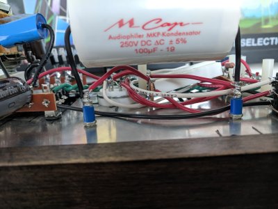
Anyway, it's a worthwhile upgrade. I went with the Mundorf capacitors, but I'm not sure the sound is $120 better. If I were to do it again, I would probably choose cheaper film caps, maybe the Dayton Audio ones, but that's just my opinion.
I'm planning on adding the speedball over the holiday weekend, so I'll post some pictures once that is done.
Anyway, I've been using it for a few days now and it sounds great! It's almost like having the Crack with Speedball, even though there's no speedball. I've got it pared up with my 600 ohm Beyerdynamic DT770 Pros (well more like 550 ohms), but the bass is very good, deep, tight and controlled. The film caps add a smoothness that electrolytic ones don't have.
Anyway, it's a worthwhile upgrade. I went with the Mundorf capacitors, but I'm not sure the sound is $120 better. If I were to do it again, I would probably choose cheaper film caps, maybe the Dayton Audio ones, but that's just my opinion.
I'm planning on adding the speedball over the holiday weekend, so I'll post some pictures once that is done.
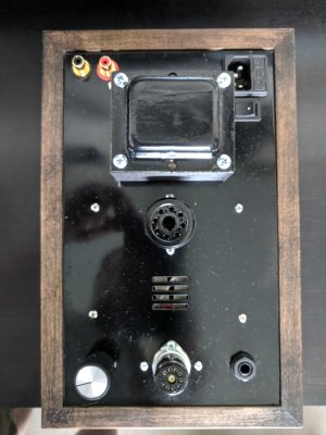
Ok, changed my mind, here's some initial pictures.
Attachments
-
 IMG_20190704_110904.jpg3 MB · Views: 111
 -
 IMG_20190704_110944.jpg3.8 MB · Views: 184
 -
 IMG_20190704_111019.jpg2.6 MB · Views: 119
 -
 IMG_20190704_111011.jpg3.1 MB · Views: 98
 -
 IMG_20190704_111055.jpg3.2 MB · Views: 76
 -
 IMG_20190704_111112.jpg3.1 MB · Views: 77
 -
 IMG_20190704_111139.jpg3.3 MB · Views: 121
So I've been listening to this mod for a few weeks now and I will say I agree that it's "all about dat bass." I have a pair of modded 600 Ohm DT770 Pro's and the bass is deep and tight, but I really hear the sub-bass. In addition I do hear more detail, but I really notice the bass response. So great mod over all!
Hi,
I'm just trying to gather safety info about handling capacitors. I know electrolytics can be dangerous when charged and that you should only handle the body of the capacitor unless you know for sure it's discharged. But what about film caps? Do they need to be discharged too before handling freely? If so, will an insulated screwdriver across both terminals (like with an electrolytic) be advisable? Thanks and pardon my ignorance.
I'm just trying to gather safety info about handling capacitors. I know electrolytics can be dangerous when charged and that you should only handle the body of the capacitor unless you know for sure it's discharged. But what about film caps? Do they need to be discharged too before handling freely? If so, will an insulated screwdriver across both terminals (like with an electrolytic) be advisable? Thanks and pardon my ignorance.
Thanks, Doc!
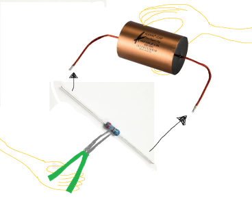
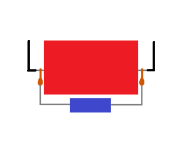
So, should I hold the resistor with insulated pliers, the cap by the body, and then join the leads? Like the attached crude picture?
"Film caps of higher values" ... How high? For example, what about the Crack's 100uF film output caps, or a power supply film bypass cap (2.2uF or less)? Thanks so much again, Doc, and I hope you and Queen Eileen are doing well during this rough time.
Attachments
If you get a 10W resistor for discharging caps, you can use an insulated pair of pliers to hold the body of the resistor to discharge things. You don't want to do that with a small metal film resistor, as you'd likely crunch through the outer coating of the resistor by grabbing it with the pliers.
Thanks, Paul!
I'll look into getting a 10K ohm 10W resistor to do the job.
Specifically, I'm looking to roll a couple of film bypass caps (1uF 400-800V) onto my last power supply film cap. With this extra time, I'm upping the dose of my crack addiction... I just want to see if I can tell any differences easily, or at all.
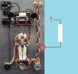
Please see attached picture. I plan to use copper alligator clips with the bypass caps for easy swapping back and forth. How would you go about doing this safely? After shutting off the amp, should I join the resistor to the caps' leads while the bypass cap is clipped on, or should I wear rubber gloves to detach the alligator clips, then use the resistor to discharge the bypass cap? Thanks for your time!")
I'll look into getting a 10K ohm 10W resistor to do the job.
Specifically, I'm looking to roll a couple of film bypass caps (1uF 400-800V) onto my last power supply film cap. With this extra time, I'm upping the dose of my crack addiction... I just want to see if I can tell any differences easily, or at all.
Please see attached picture. I plan to use copper alligator clips with the bypass caps for easy swapping back and forth. How would you go about doing this safely? After shutting off the amp, should I join the resistor to the caps' leads while the bypass cap is clipped on, or should I wear rubber gloves to detach the alligator clips, then use the resistor to discharge the bypass cap? Thanks for your time!
Attachments
The way I do it is to hold the resistor with insulated needlenose pliers by the body, then discharge the power supply to the chassis. It's a lot easier to do it that way rather than trying to get a big 10W resistor connected between B+ and ground.
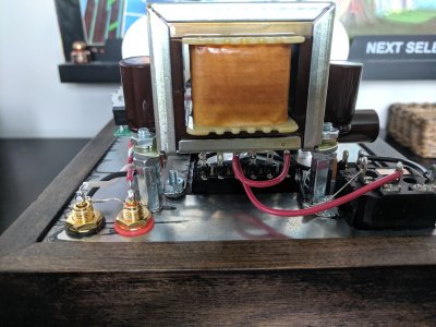
You'll probably find that it's super easy to use terminal 5 on the octal socket.
Okay, just to be clear, the process for safe cap discharge goes:
1) Power off amp
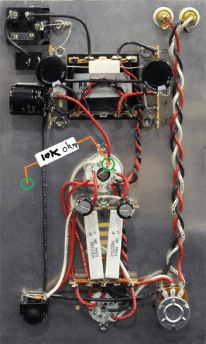
2) Touch 10K ohm resistor to octal terminal 5 & anywhere on chassis (please see photo to verify)
3) freely handle alligator clips or leads of any cap in the amp
...or for a specific cap, touch resistor ends to each lead of the cap to be handled.
1) Power off amp
2) Touch 10K ohm resistor to octal terminal 5 & anywhere on chassis (please see photo to verify)
3) freely handle alligator clips or leads of any cap in the amp
...or for a specific cap, touch resistor ends to each lead of the cap to be handled.
Attachments
More digging led to my finding this post by Paul Joppa (about discharging 220uF 250V PS caps):
________________________________________________________________________
Re: Building a capacitor discharger - what size resistor to use?
« Reply #1 on: January 26, 2012, 12:07:35 PM »
"Perhaps we should look for a resistor that will survive even if the circuit is still accidentally powered. Let's say you want to use a 5-watt resistor; then since power equals voltage squared over resistance, the minimum resistance is 8000 ohms. The time constant RC is less than 2 seconds, so if you leave it connected for 10 seconds (5 time constants) the voltage will decay by a factor of 175 (e to the 5th power) - i.e. to a bit over a volt. 10K is probably easier to find.
"For a 1 watt resistor, you'd need 40K and it would take 50 seconds to discharge. I'm not that patient, myself."
________________________________________________________________________
So, again, to be perfectly clear, the process for safe cap discharge should go:
1) Power off amp
2) Touch 5W 10K ohm resistor to octal terminal 5 & anywhere on chassis for 10 seconds (please see photo to verify)
3) freely handle alligator clips or leads of any cap in the amp
...or for a specific cap, touch resistor ends to each lead of the cap to be handled for at least 10 seconds.
Is this correct? Thanks for bearing with me.
________________________________________________________________________
Re: Building a capacitor discharger - what size resistor to use?
« Reply #1 on: January 26, 2012, 12:07:35 PM »
"Perhaps we should look for a resistor that will survive even if the circuit is still accidentally powered. Let's say you want to use a 5-watt resistor; then since power equals voltage squared over resistance, the minimum resistance is 8000 ohms. The time constant RC is less than 2 seconds, so if you leave it connected for 10 seconds (5 time constants) the voltage will decay by a factor of 175 (e to the 5th power) - i.e. to a bit over a volt. 10K is probably easier to find.
"For a 1 watt resistor, you'd need 40K and it would take 50 seconds to discharge. I'm not that patient, myself."
________________________________________________________________________
So, again, to be perfectly clear, the process for safe cap discharge should go:
1) Power off amp
2) Touch 5W 10K ohm resistor to octal terminal 5 & anywhere on chassis for 10 seconds (please see photo to verify)
3) freely handle alligator clips or leads of any cap in the amp
...or for a specific cap, touch resistor ends to each lead of the cap to be handled for at least 10 seconds.
Is this correct? Thanks for bearing with me.
Attachments

You're missing the step where you take your meter and measure the DC voltage left in the supply.
For a power supply like the Crack, I don't worry much if there's 10V or less left in the supply, that's low enough for me. In a low voltage power supply with tens of thousands of micro-farads of capacitance, that isn't necessarily the case.
For a power supply like the Crack, I don't worry much if there's 10V or less left in the supply, that's low enough for me. In a low voltage power supply with tens of thousands of micro-farads of capacitance, that isn't necessarily the case.
baseonmars
New member
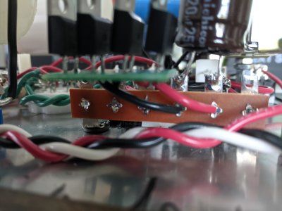
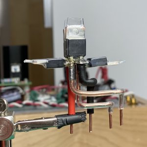
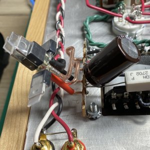
Here's my take on some free form soldering to replace the rectifier diodes with Cree Schottky diodes.
Each diode runs at around 31.5ºC after an hour or so of use. The copper legs are bound in place with a single strand of very thin wire then soldered in place. There's a bit of UV cure resin thrown in for extra mechanical strength.
I wasn't entirely sure this was a good idea when I started but I think it turned out pretty well. There are sound improvements to be heard in term of less weird high pitched noises which I'd attributed to RFI - maybe it was just a dodgy solder joint - I guess I'll never know for sure. This plus some bypass caps, diode grounding, a shield for the 12AU7 and an alps pot have take the crack as far as I want to. Maybe one day I'll take it all out and try each step in a different order to figure out where the biggest gains were had.
The noise floor is incredibly low and the sound is exactly where I want it. I find myself listening all day long.
Attachments
baseonmars said:in term of less weird high pitched noises which I'd attributed to RFI
If you implemented the modification to use antiphase diodes to break the signal ground and earth, then that would get rid of weird high pitch noises.baseonmars said:diode grounding
baseonmars
New member
Paul Birkeland said:If you implemented the modification to use antiphase diodes to break the signal ground and earth, then that would get rid of weird high pitch noises.
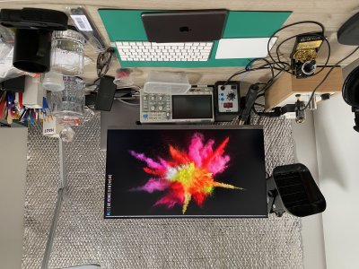
Hi Paul, I did! They removed some of the noises but not entirely. I ended up putting a sheet of aluminium insulating foil up on a wall and that got nearly all of it (I look like a loon, but 100% the government can't see my thoughts anymore
") )... in all seriousness there's a cell tower about 100 feet from our house.
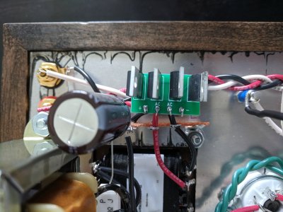
)... in all seriousness there's a cell tower about 100 feet from our house.I made each change separately - tube shield, antiphase diodes to ground, bypass cap, cree diodes and finally an additional bypass cap. The noises stopped after the cree diodes but I already had the caps at this point (2.2uf and 220nf I believe) so I added the to the final electrolytic. I think the tube shield had the largest effect but it made some other subtle sounds more apparent.
I was done... in reality I'm going to add some copper shielding inside the case - as fond as I am of the silver foil it's starting to attract the wrong kind of attention.
Attachments
Similar threads
- Replies
- 13
- Views
- 3K
- Replies
- 44
- Views
- 70K