Low voltage on finished Crack (repost)

tsuid1

New member
Hi all, I posted about this before, but for some reason, the website is giving me a hard time replying and updating, so I decided to post again with more details.


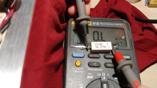
Like the title says, just finished building the crack. I checked the resistance this morning and the numbers all matched the manual's.

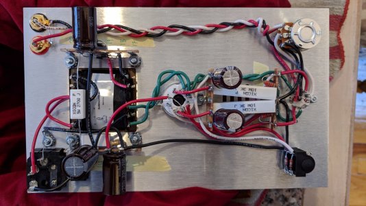
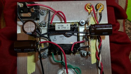
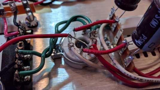
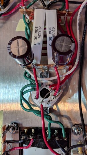
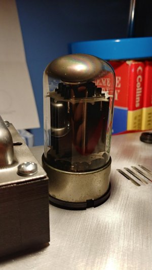
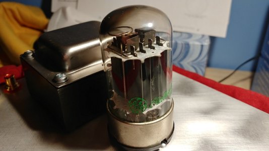
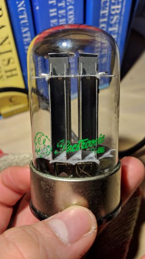
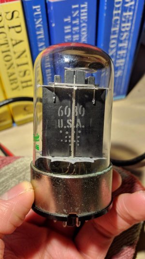
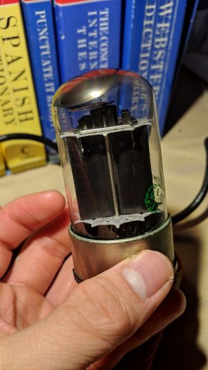
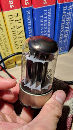
Last night I was performing the voltage test with tubes installed. The 12u7 tube glows with no issue but the 6080 doesn't glow at all. The LED's were on for five minutes, but then they turned off and hasn't turned back on since.

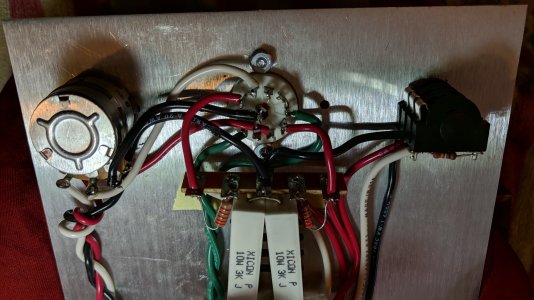
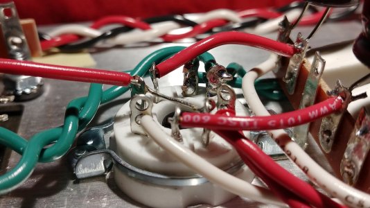
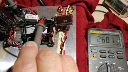
The voltage also seems to be pretty low compared to what the manual says. Also worth noting that I checked the orientation of the 8 pin socket and it's pointing towards the vent holes as instructed. As for the L+N voltage test, my meter measured 121v, so I followed the instructions on page 25

1- 2.30v
2- 2.30v
3- 0v
4-2.3v
5-2.3v

6-0v
7-0v
8-0v
9-0v
10-0v

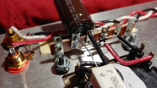
Also added photos below.

Thanks
 

Attachments

  • Crack trouble shoot 1.jpg
    Crack trouble shoot 1.jpg
    427.9 KB · Views: 14
  • crack troubleshoot 2.jpg
    crack troubleshoot 2.jpg
    1,010.6 KB · Views: 6
  • crack troubleshoot 3.jpg
    crack troubleshoot 3.jpg
    425.6 KB · Views: 7
  • crack troubleshoot 4.jpg
    crack troubleshoot 4.jpg
    737.2 KB · Views: 8
  • crack troubleshoot 5.jpg
    crack troubleshoot 5.jpg
    643.8 KB · Views: 8
You might need to check the file size of the pictures since there’s an attachment limit.
 
tsuid1 said:
The 12u7 tube glows but not the 6080. I'll try to add more solder.

In addition to a bit more solder, it may be necessary to add a bit more heat to the junction so the solder flows nicely leaving a clean and shiny joint behind.  Higher heat for a shorter period of time is often an effective approach if you have the ability to adjust the temperature of your soldering iron.
 
Here are some pictures of the 6080, 8 socket and 20u and 21u.

Does this mean I have to reheat the solders at 20u and 21u? How long should I reheat them for? I just checked them and they were both filled before I resoldered anything.
 

Attachments

  • crack 9.jpg
    crack 9.jpg
    300.9 KB · Views: 7
  • crack 8.jpg
    crack 8.jpg
    140.7 KB · Views: 5
  • crack 7.jpg
    crack 7.jpg
    193.9 KB · Views: 9
  • crack 6.jpg
    crack 6.jpg
    526.6 KB · Views: 11
Just a few seconds should do it, usually not more than 4-5s depending on the overall mass of what you are trying to heat.  It you watch carefully with a bright light, you'll see the solder melt when you apply the iron and you'll also see the melting spread across the solder joint as you heat it.  If you need to add more solder, this is the time.  Then, just remove the iron and let it cool on its own and you should be good to go. 

If you have any doubts, there are TONS of youtube videos about forming proper solder joints.  If you are new to soldering, it sometimes takes a little bit of practice, but you'll get it!
 
Ok, before I had a chance to solder, my dad who is an electrician checked on the wiring. Everything seemed fine, but we found that the 5w 270ohm resistor by terminal 13 and 14 is open. Could this explain why the amp isn't working properly aside from soldering those two joints?
 

Attachments

  • open resistor.jpg
    open resistor.jpg
    471.1 KB · Views: 11
  • open resistor 2.jpg
    open resistor 2.jpg
    666.6 KB · Views: 10
tsuid1 said:
... we found that the 5w 270ohm resistor by terminal 13 and 14 is open. Could this explain why the amp isn't working properly aside from soldering those two joints?

Yup. With an open 270R resistor, you'll have no high voltage power supply. You'll want to replace that resistor.

cheers, Derek
 
Definitely replace that resistor.  Any 200-300 ohm 5W resistor will do.

Also do post photos of the 6080 you have in the meantime.
 
Sure no problem. Images are below.
Just contacted the replacement service. Hopefully will have it by Saturday. I'll probably try to look for it in a local hardware store. How much does it usually cost?
 

Attachments

  • tube.jpg
    tube.jpg
    542.8 KB · Views: 7
  • tube2.jpg
    tube2.jpg
    233.5 KB · Views: 2
  • tube3.jpg
    tube3.jpg
    106.2 KB · Views: 3
  • tube4.jpg
    tube4.jpg
    568.4 KB · Views: 6
I'm curious why a 5w sandcast resistor is open...  That's a pretty beefy resistor and I've never come across one that was DOA before usage.  Proceed carefully and check voltages and wiring as thoroughly as possible.  There may be a fault somewhere that caused that resistor to burn up.  If there is a problem, installing a new one will simply lead to it burning up as well. 

If you don't find an obvious wire fault, keep an eye (a temp probe?  a finger?) on that resistor for the first minute or two after you power up to look for "extra" heat.  Given that it's a B+ smoothing/dropping resistors, a temp of 30-50c might be normal.  30-40c means you can keep a finger on it indefinitely (watch out for the voltage - don't touch the lead!).  50c is a finger on it for <5s or so.  I'm gonna guess that you really shouldn't be seeing anything north of 70-80c.
 
I thought the same thing, but the open resistor doesn't show signs of having been cooked. The writing on the body is still black, clear and even; and there is no discoloration of the leads from heat stress. Maybe a lead broke/disconnected inside the body - either at manufacture or subsequent twisting?
 
Can you measure the DC resistance between pins 7 and 8 on the tube itself?

It is weird that the resistor is open, but I have seen that happen once in the last 25 years. 
 
Both of the above points (resistor doesn't appear burned and it seems rather rare to a new resistor that is DOA) make me think the problem lies elsewhere.  Are you getting good contact with your probes on the resistor leads?  Maybe some steel wool or gentle sand paper cleans something off of the leads that was causing a problem?

If this is not the case, your problem is most certainly elsewhere.  Search logically and methodically and start with most basic elements.  Work from the schematic and with your meter, cross off verified connections and note voltages on the diagram and move on.  You know generally where to look.  Start with the transformer, verify you're getting good AC voltage into it and good AC voltage out of it.  Check fuses, solder joints, voltages at each PSU cap, across the bleeder resistor, etc.

You'll find this - be logical, check every component and every wire, one at a time.     
 
tsuid1 said:
I'll probably try to look for it in a local hardware store. How much does it usually cost?

Mouser sells them for about a $1: https://www.mouser.com/ProductDetail/Yageo/SQP500JB-270R?qs=%2Fha2pyFaduiKZkvBfzT47gv2toBgzYfDhi5ak38cJcV7ykBbdTaI9Q%3D%3D

A North American hardware store selling construction tools and supplies is very unlikely to carry them. But a local electronics supply shop would most likely have something that would work - and maybe charge a bit more. Maybe 2$.  As PB wrote, anything 200-300 ohms and rated 5W will do.

cheers, Derek
 
Back
Top