Low staticky crackle on right channel (solved)

Caucasian Blackplate said:
OK, those are working voltages!

The intermittent sound is still there though on right channel :(

Is there anything else than reflowing all joints for the 30th time that could help?
I think I will reheat and desolder the joints and warm and apply new solder. The first soldering iron I was using was super bad and didn't keep the heat well enough. I have heated all joints numerous times but that just doesn't help

Edit:/ So I changed the wire from potentiometer to 9pin middle again ja made sure the connection is good. Also resoldered T3. 0 change.

I took the solder out of the joints with wick, reheated and added smaller amout of solder cos I thought maybe I used a bit much on the first times. Still the same sound is there even after not just reheating but resoldering all the joints. I also improved some of the subpar physical connections
Voltages changed ever so slighty after this overhaul. At some point during this there was all sorts of weird hisses ja sounds from both the channels at different points but now left channel is dead quiet again ja right still has the same crackle .
Only thing I haven't done is roll another 6as7g in.

 
The chopstick test is great for finding broken wires.

You might have environmental noise that is only being picked up in the right channel.  Can you pack your Crack up and take it to work with you for the day?  That would give an alternate data point in terms of noise performance.
 
Caucasian Blackplate said:
The chopstick test is great for finding broken wires.

You might have environmental noise that is only being picked up in the right channel.  Can you pack your Crack up and take it to work with you for the day?  That would give an alternate data point in terms of noise performance.

Sure I can test that on Monday. That's what I thought. 'Im just running ideas since I resoldered the whole circuit, changed a couple of wires and the issue still persists. I'm mostly testing without RCA's connected but that doesnt change the sound at all.
 
I went to the basement where the bomb shelter / storage room is and its the same.
I was wondering if maybe the fact that I live in an older apartment where only the kitchen and bathroom has to have grounded Schuko sockets matter, but seems like it doesnt.

Should I still go the circuit over one more time? It would be nice if there was even the slightest of change after all that soldering and stuff, but there been no improvements

Only wires that maybe could have an issue and that I haven't changed are the ones connected at T3 but no matter how much I try and yank or poke the wires there is change.
 
Oh man, you're giving me flashbacks. I lived in a high rise apartment building when I was in high school in the 70s. I'm remembering the fallout shelter signs in the basement.

Unfortunately it's always harder to diagnose this kind of thing without being able the hear the noise in person. I'm gathering this is a new build? Some times the noise is coming from a tube and may go away as the tube cooks in from several hours of play. Or maybe it's a socket connection. Along with testing the wire connections underneath, have you tried rocking the tubes in the sockets a little to see if that makes the noise come and go? Cleaning the tube pins can sometimes help.
 
Doc B. said:
Oh man, you're giving me flashbacks. I lived in a high rise apartment building when I was in high school in the 70s. I'm remembering the fallout shelter signs in the basement.

Yeah exactly like this!
It is a new build indeed.

I did clean the tube pins but that didn't help. Manipulating the tubes has no effect. Only thing I think affects is when I poke around the red wires on the underside, but there is not 1 place that makes it any more than the other. Its like the whole red path makes it. Or it just happens to crackle at that specific time.

soldered speedball again and voltages improved a bit:

Small board:

OA 70
IA 191
B-A/B 0
IB 190
OB 69

Big board:

OA 106
OB 106
G 0
B+ 193

Edit:/
MAN this amp is baiting me so hard. I was doing reflowing and whatnot, turned the amp over added the tubes and did some more chopstick testing. I hear the same freaking sound again and then I see I forgot to add solder to the connection from hp jack to 6L, I poke the connection and when i press the wire from the middle down with my finger the amp goes dead silent. The quietest I have ever heard it. Im like this is it. The 6L end of the terminal had the wire just go straight to the hole and soldered, so there was no proper physical connection. I went and bent the wire over the terminal and pressed tight, soldered and I was SO HOPEFUL. I power the amp and everything is the same as before. Even the voltages went up the old where they are a bit higher. What are the changes that after I have redone all circuits, swapped wires etc. etc. there would still be a cold solder or a bad wire after the chopstick test has no effect, and I can sometimes make the sound go away with wiggling the small tube, but so I can with wiggling random wires from underneath.
Is there any chance that the 6as7g could be the culprit?
 
Caucasian Blackplate said:
I'd let the amp run for 50 hours to see if the tubes cook in.

Ill try it! Maybe I just nicked all wires that affect right channel and none of the left channel ones :D I had 1 not that good physical connection on the red wire going from A7 to the potentiometer(I had just weaved the wire through the terminal in the jack but hadn't fold it over.) That didn't do anything. Ill let the amp run now on its own for a while. Do i keep headphones in it and play music or just let it go on its own?
 
You can just let it idle.

If after the 48 hours the noise persists, try to lay hands on a film capacitor that's between 0.1uF and 1uF and rated at 250V.  These are pretty easily found at your local electronics store, and will be handy for another test.

-PB
 
Julyan9 said:
I really appreciate the time you have taken to try and help me with this issue.

Just a side note.  Wow, this support is so impressive.  I can't remember ever seeing this level of support for a product by the developers and designers themselves.  This is great.  I'm having fun following all these Crack builds as I go through mine at a snail's pace.  I just wanted to say it's noticed and appreciated even if not my project directly; you guys are the best.
 
Thanks very much for the kind words, we really appreciate it. We figured out years ago that the moment of truth when you start the project up can be the tipping point on whether you get satisfaction from the project. Everyone has to climb the learning curve, and everyone makes mistakes. So that particular moment when something doesn't work right and frustration can start to set in is what we try to be most sensitive to. The kits are designed with this in mind and the layout, and assembly and test procedure reflects the desire to make it as easy as possible to get through the rough bits. Having a place to ask questions is the other important ingredient in the recipe.

With the Crack kit what we want to do is help people learn the basic skills like soldering and using a meter, and deliver a solid design that sounds good. There are plenty of universities teaching electronics theory if you want to climb higher up the curve and become a designer. I like to think we have inspired at least a few customers to head in that direction.
 
I really really want to find the cold solder from the kit but its just so annoying when nothing happens after tens of tries :D
 
We also learn a lot from providing this tech support.  When we revised the Crack 1.0 to the Crack 1.1, almost all of the changes were in response to common trouble spots for the average builder.  As we put out new kits, those changes just keep getting folded into everything. 

 
Does it matter which green wire goes to which terminal from and to B7/B8? I think I just kinda winged it since the manual just says to get the wires from 7 and 9 terminals of the transformer to B7/B8

Edit://
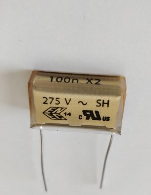
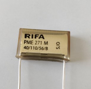
So I went to the local store and they only had the one I have attached the picture of. When I got home I remembered that it should have been a film cap instead so that maybe doesn't suit the need here?

If I order this ERO / VISHAY / ROEDERSTEIN MKT 1813 470NF (0.47UF) / 250V (MUSTARD STYLE) POLYESTER FILM CAPACITOR, AXIAL it will be the right one yes?
 

Attachments

  • cap1.jpg
    cap1.jpg
    414.2 KB · Views: 3
  • cap2.jpg
    cap2.jpg
    389.9 KB · Views: 2
That will work.  Temporarily solder that cap between 1U and 5U, then let us know if the behavior of the static changes.  Be sure to leave the leads super long, as we may end up putting this cap in all sorts of different places as we check each bit of the circuit.
 
Caucasian Blackplate said:
That will work.  Temporarily solder that cap between 1U and 5U, then let us know if the behavior of the static changes.  Be sure to leave the leads super long, as we may end up putting this cap in all sorts of different places as we check each bit of the circuit.

1U and 5U was no cigar.

I got some better solder and wick, and I was bored so I went over the red path again, the solders look much better and shinier, but it didn't help with the initial issue. Last solder I had was Sn60Pb39Cu1 and this one is Sn62Pb36Ag2
 
Back
Top