You are using an out of date browser. It may not display this or other websites correctly.
You should upgrade or use an alternative browser.
You should upgrade or use an alternative browser.
Low staticky crackle on right channel (solved)
- Thread starter Julyan9
- Start date
The next thing to do is to find a wooden chopstick and a cheap pair of headphones. With the cheap headphones on and plugged into the amp with the amp upside-down, poke around the amplifier with the wood chopstick until you can activate the noise, then you'll know where the issue is.
Caucasian Blackplate said:The next thing to do is to find a wooden chopstick and a cheap pair of headphones. With the cheap headphones on and plugged into the amp with the amp upside-down, poke around the amplifier with the wood chopstick until you can activate the noise, then you'll know where the issue is.
Yeah I've been doing that for days. The noise is not there all the time and some times very faint. I cant find any more connections that make it come or go. I've fixed all I thought were the issue but apparently werent. Could be any of the red wires. I go all the red ones over once more.
If the noise is not persistent, it would be a good idea to look into external sources. For example, any appliance with a motor in it (fridge, washing machine, dryer, bathroom fan) or a switching power supply can set things off. Your phone and/or wifi router can also broadcast periodic noise that can get into components.
Generally folks find it helpful to take their amp to a different location (office or a friend's house) to see if it behaves in the same way in a different environment.
Generally folks find it helpful to take their amp to a different location (office or a friend's house) to see if it behaves in the same way in a different environment.
Did all the red ones again for the tenth time. Still the same. Yeah its not persistent. Sometimes the amp can be silent for a couple of minutes or more before it happens again. Make the chopstick test very difficult.
I tested it in another room and switched off wifi. Still there. If I don't get this to work during the weekend I'm just going to send it back and pay for the repairs. I will be baffled if its still a cold solder when I have reflowed all joints 10 times and swapped couple of the wires.
I tested it in another room and switched off wifi. Still there. If I don't get this to work during the weekend I'm just going to send it back and pay for the repairs. I will be baffled if its still a cold solder when I have reflowed all joints 10 times and swapped couple of the wires.
With speedball installed should I still get the 2.9K ohm resistance from 12U to B3 and B6? I cant get a reading anymore. Same goes for 12U to terminal 7 and 9. It passed the test earlier.
Also from 12U to Left RCA center pin I get 115 but to Right its 122.5
I may be grasping at straws here but I'm running out of ideas
Took new readings from the Speedball circuits aswell (havent touched these since the problem was even before speedball, which i realized only after I installed speedball, thought I fixed it before)
Large Board OA 63.7 OB 60.7 G 0 B+ 137.7
Small Board OA 33.8 IA 138 B-A/B 0 to 1 IB 137.7 OB 37.5
These are by using 234V wall socket
Your boards are not working properly. Getting 38V out of the small board is likely the root cause of the problem. Your high voltage rail is also low.
Can you pull the 6080, leave the 12AU7 in, then let me know what the OA and OB voltages are on the small board?
Can you pull the 6080, leave the 12AU7 in, then let me know what the OA and OB voltages are on the small board?
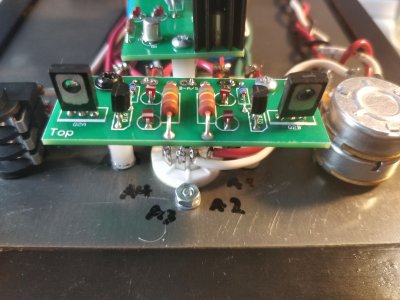
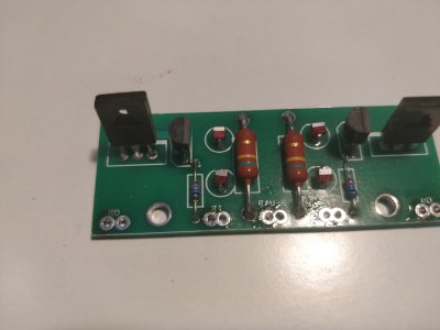
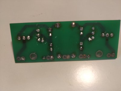
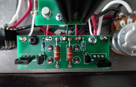
Flip that board over and resolder all of the solder joints, especially on the MJE350. Can you post some photos of that area of the build? Are the LEDs on the socket lighting?
You're only passing about 1/3 of the current through the small board that you should be.
You're only passing about 1/3 of the current through the small board that you should be.
Yes sir, all the LED's are working, the ones on the small board seem a bit dim though. I will go over the small board now and measure again after
Went over the soldering, IB and IA got up to 175 now but OB and OA are the same as before.
Edit. Tried to reflow the center legs again couple of times to no avail. The solder moves around the leg but the numbers are the same from OB and the center leg
Went over the soldering, IB and IA got up to 175 now but OB and OA are the same as before.
Edit. Tried to reflow the center legs again couple of times to no avail. The solder moves around the leg but the numbers are the same from OB and the center leg
Attachments
IB and IA voltages function independently of that board. If they have changed significantly over the course of your work, that indicates a loose or broken wire that is acting as a bottleneck to the circuit.Julyan9 said:Went over the soldering, IB and IA got up to 175 now but OB and OA are the same as before.
There's also still a small possibility that there's still a grounding issue in your amp. Try measuring the OA and OB voltages with terminal 3 as your ground reference (or B-A/B on the small board if that's easier).
-PB
Julyan9 said:Small Board OA 33.8 OB 37.5
Which terminal were you using for ground before 3? For the second set of results, you have the 12AU7 in the socket hopefully (like the first set of measurements).Julyan9 said:OB 159 and OA 148 from terminal 3. Same results from B-A/B
Caucasian Blackplate said:Which terminal were you using for ground before 3? For the second set of results, you have the 12AU7 in the socket hopefully (like the first set of measurements).
"OA 28, OB 31" This was the result using the 12AU7 only
"
Large Board OA 63.7 OB 60.7 G 0 B+ 137.7
Small Board OA 33.8 IA 138 B-A/B 0 to 1 IB 137.7 OB 37.5"
These were taken with both tubes on like the manual suggested.
I was using 12U as ground before 3.
If your OA/OB voltages on the small board with just the 12AU7 installed are different depending on whether you are grounded at 3 or terminal 12, then terminals 3 and 12 are not well connected and you need to reflow all of the solder joints on the ground path (black wires from the RCA jacks to the volume pot, volume pot to terminal 3, terminal 3 to headphone jack/9 pin center pin, headphone jack back to the power supply, and black wires in the power supply back to the diode bridge).
I would reflow all of the solder joints on the small PC board. Having that super low voltage indicates that nearly no current is flowing through the tube.
Caucasian Blackplate said:I would reflow all of the solder joints on the small PC board. Having that super low voltage indicates that nearly no current is flowing through the tube.
Nvm the numbers are actually different, ill reflow the ground path now.
so from terminal 12 and terminal 3 to OB on small board 159 and 147.6 to OA
The problem is I confused the 12U to the transformer 12 pin and not to the 12 on terminal strip.
The numbers from terminal strip 12 are way higher.
both tubes on
small board: OB 162 OA 150.2 IB 425 IA 425 B-A/B 0
big board: OB 232 OA 241 B+423 G 0
I did the check to A2/A7 and both sit at 0 with all LED's lit
If the heater (AC) supply ground is tested from E to B7/B8 all ground resistance path checks passed.
Is there a path that should end to T22?
Edit://
What could cause the high voltages?
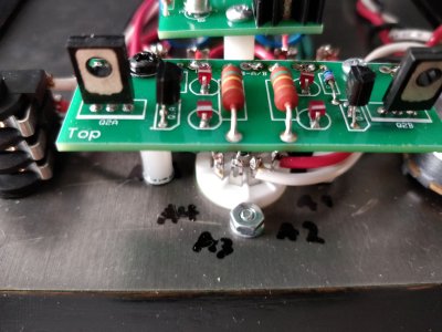
Pics of the small PCB, I can't get the solder to go nice and smooth and shiny on the top side of the board. I've tried warming it more and more but nothing seems to happen. The solder is moving on both sides of the board.
Attachments
OK, those are working voltages!
Similar threads
- Replies
- 7
- Views
- 132
- Replies
- 9
- Views
- 221