Low staticky crackle on right channel (solved)

Julyan9

New member
Hello!
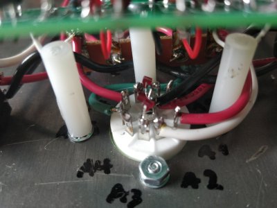
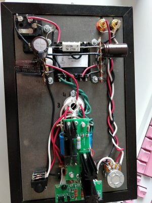
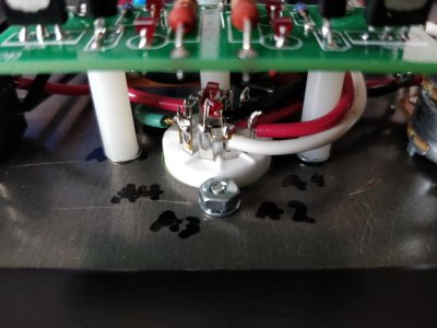
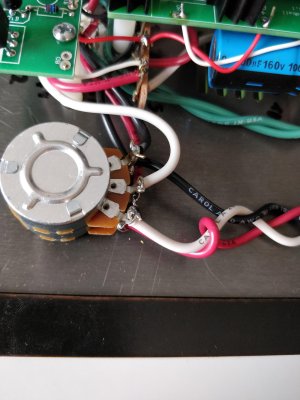
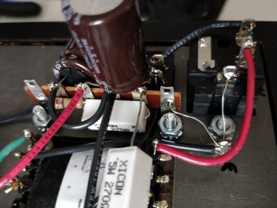
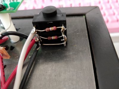
I finished the crack around a week ago. I absolutely love it. My problem is that after a few days of listening a slight cracking sound appeared on the right channel. I have re-soldered all the connections, and there were some bad ones on 3L, 1L, the grounding point near the power inlet and the 2 black wire meeting point on the headphone jack.
At first I thought I solved the issue when I soldered the grounding jack and I didnt hear the crackling anymore. I then added the speedball but the noice was there again. Then I left the amp on for 8 hours, and when I woke up the sound was a lot louder than before, it was very prominent. I had to go to work so didnt have time to chopstick it at the time. Then after the amp had been on continously for 16 hours there was no noise again when I was starting to debug it. I wait for a couple of hours and its there again but its very silent and it comes and goes so its hard to test what connection might be making the sound. Only time something changed when I was poking the connections, was when I found the loose connection on the headphone jack. I tried to scotchbrite the 12au7 pins but that didnt help either. I ordered a new 12au7 to see if it helps. Sometimes the crackling varies when I poke the 12au7 and sometimes it doesnt so I dont know if that is the cause or not. I have gone over the solderings over so many times now that I dont know where to go with that. Any tips on certain points I should re-check one more time?

Also the crackling doesnt happen right after I turn on the amp but it comes and goes after the amp has been warming for a while. Volume pot position doesnt affect the intensity of the sound. 

Thanks for any tips. 

edit.// To add I'm using Computer->R2R-11 dac output->Crack->HD600. I have tried it with a different cable to the HD600 and with G4me zero senn gaming headset and the same thing happens. The sound was first coming from the left channel, but im pretty sure that I didnt have the hd600 connected the right way when I first used it.  IT would be weird for the sound to jump to other channel after some re-soldering wouldnt it?
 
It might help if you can post some photos of your build. 

This is indeed almost always a solder joint not doing its job.
 
Its surprisingly difficult to take photos of components. I first tried with my dslr but that wasnt going to happen.
Noticed that B1 needs some more solder for sure.
 

Attachments

  • picture1.jpg
    picture1.jpg
    1.4 MB · Views: 29
  • picture8.jpg
    picture8.jpg
    1.3 MB · Views: 15
  • picture7.jpg
    picture7.jpg
    375.2 KB · Views: 8
  • picture6.jpg
    picture6.jpg
    1.5 MB · Views: 13
  • picture5.jpg
    picture5.jpg
    1.4 MB · Views: 18
  • picture4.jpg
    picture4.jpg
    1.4 MB · Views: 12
  • picture3.jpg
    picture3.jpg
    1.4 MB · Views: 17
  • picture2.jpg
    picture2.jpg
    1.1 MB · Views: 19
A little more solder and more heat will get those to flow out properly and I think your noise will go away.  I'd also go through and trim and leads that are poking out.  I've circled three in this photo that could cause some serious problems down the road.

-PB
 

Attachments

  • crack shorts.jpg
    crack shorts.jpg
    369.2 KB · Views: 67
Yeah I will fix those tomorrow. I'll also add solder to B1 and see if it helps any. My iron just broke on its own so I have to get a new one :( 
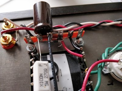
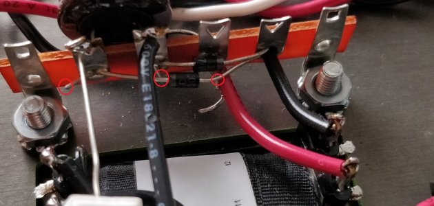
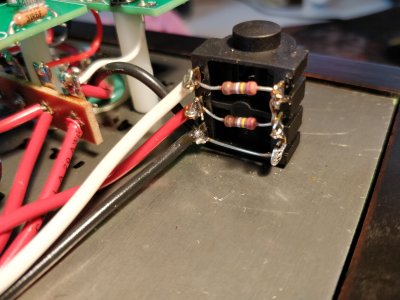
I didn't trim all the leads yet because the pliers I'm using are bad and I can't fit to that narrow place with them.
 
Pliers? You need a pair of "flush cutters", check Google images. Pay a little more for extra life and reliable cutting. The ones with black "flat" blades are usually very sharp but prone to breaking off a blade if try and cut something a bit too thick.
 
Deluk said:
Pliers? You need a pair of "flush cutters", check Google images. Pay a little more for extra life and reliable cutting. The ones with black "flat" blades are usually very sharp but prone to breaking off a blade if try and cut something a bit too thick.

Yeah sorry english is not my first language, i meant flush cutters. I took the amp with me to work and used the gear there to go over all the solders and then used some ESD flush cutters to trim the leads as short as I could. For some reason I think the amp sounds a bit better now and I have not been able to hear the crackling sound anymore. Ill give it this evening and see if it appears again.
 
I think the origin of the sound may be the A3 connection. I think its the only tab i have forgotten to redo. The sound appeared when i took a toothpick next to the led and while poking at the connections a2-a5 region.
 
The A3 connection looked OK in your photos.  The center pin of the 9 pin socket might be a different story though.
 
I re-did the center pin but now that I looked at it again I think the black wire could use some more solder. Maybe poking at the lower A connections move the center pin and that makes the sound. I will be wiser tomorrow. Thank you for tips and help.
 
Now after some re-flowing on the smaller tube socket, the sound is now coming from left channel instead of right. So i did something right and something wrong while doing this. Still same channel. The sound is always more prominent when poking around the socket, I just dont know what more to do about it. Surely the issue is in that region since poking the connections makes the sound happen.
 
Post another picture. Today is the 4th of July holiday in the US so you might not get a reply from the Bottlehead team today.

Try wriggling the wires one at a time going to the 9 pin socket to see if you can identify one that is causing the issue. It’s possible to nick a wire when stripping which later breaks just under the insulation. That could be your problem if one wire causes the problem but it’s well soldered to the socket.

Beyond that be patient and wait for the BH team to respond.
 
I detached the black wire coming from the potentiometer to the center pin and replaced it, didnt help, poked some more and A3 might have been making some noice. now there is a slight hiss on left channel that wasnt there before. right channel still doing the same thing as before.
 
I changed the red wire also going to A6 and properly crimped it over but that didnt help either. I've been putting off fixing A9 cos I think I need to remove the center black wire to make room. Attached a pic of the small socket
 

Attachments

  • IMG_20180704_201013.jpg
    IMG_20180704_201013.jpg
    4 MB · Views: 31
I'm running out of ideas what to do I did the grounding test.

Measure resistance through this grounding path:


It jumps to the 2 left lugs of the volume pot, measure both lugs.  Then it jumps to the back to the RCA jacks.  Measure to the outer jacket of the RCA jacks.  OK

From the top left lug of the volume pot there is a grounding jumper to the two bottom lugs of the headphone jack.  The jack in the picture may be different than what is being delivered today.  Measure to both headphone jack lugs. OK

The power supply ground comes from those bottom headphone jack terminals to terminal 12.  Measure to terminal 12.  From there it jumps to terminal 14 and ends at terminal 20.  Measure to both. Cant get a reading from bottom hp jack terminals to 12. 12->14 also blank and 14->20 too. Ground ok from hp jack lower terminals to 20

Also from terminal 3 you go to the center lug of the 9 pin tube socket.  This is the ground route for the LEDs in the cathode circuits.  Measure here. OK

The heater (AC) supply gets its ground from a wire from transformer terminal 4 to terminal 22.  Measure both. This I didn't understand, 4->22 gives no reading but what is supposed to be the starting point of this.

Other points that should be a solid ground are pin 8 of the large tube, pin 4 and 5 of the small tube, T8, T11, T14, T16, T17, T20, T22 and the ground post on the IEC power connector, the one with the bare wire to the chassis. OK if i did this part correctly
 
Julyan9 said:
Cant get a reading from bottom hp jack terminals to 12.
These are connected by a piece of wire.  If they don't measure as being connected by that piece of wire, then you have a solder joint at one end or the other that isn't doing its job. It's very common for the solder joint on the headphone jack end to not flow around both wires, so I would check there.


Julyan9 said:
The heater (AC) supply gets its ground from a wire from transformer terminal 4 to terminal 22.  Measure both. This I didn't understand, 4->22 gives no reading but what is supposed to be the starting point of this.
What version of the Crack do you have? (If there's green wire in it, it's the newest one).  The 6.3V AC winding gets its ground from the ground lug back by the IEC power entry module unless you have a previous version of the kit.  The place to measure this reference would be B7 and B8.
 
HP jack to 12 is fixed now, i still cant get anything from 12->14 or 14->20 but hp jack to 20 works fine.
Also from IEC ground lug to B7 and B8 is ok
 
Could that also help with the sound on other channel or are those two completely separate issues?

All grounds are good. Don't tell anyone I was trying to measure them from the transformer instead of the terminal strips  8)

Attached a pic of the HP jack as of now. Im going to reflow everything one last time and see if that helps.

Left the amp on overnight again, same thing happens . When I use the amp normally and it's on like 4-6 hours the sound is barely noticeable. When I leave the amp on overnight and it has time to warm, the sound is very prominent after.

edit no5. Again I reflowed over the whole circuit with 0 change
 

Attachments

  • IMG_20180705_202602.jpg
    IMG_20180705_202602.jpg
    3.7 MB · Views: 18
Back
Top