left Paramount now blowing a fuse

rbc3

New member
After many happy hours of working well and tube rolling, my left channel Paramount is now consistently blowing a fuse.  The last time it was working, I was listening to headphones with a banana plug adapter.  I was listening to AKG K1000, LCD2.2, and HE-500 cans to compare how well the Paramounts drive these different cans.  My adapter is a banana to 4 pin XLR that I use to quickly switch between cans.  I am pretty sure I was running 1950s Western Electric 396A D getter black plate input tubes which are my newest tube purchase but had been running well for at least 5 hours when driving speakers. I was also running KR VV300B output tubes, also ran successfully for at least 20 hours in the Paramounts driving my speakers.

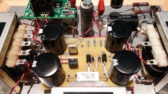
I checked around the amp for any weird connections or crossed wires and then replaced the stock tubes.  I also went back through the resistance check and it checks out exactly as before.  I noticed an arc from the pins of the AC power socket to the fuse when switching the amp on which must be what is blowing the fuse.

I figure the most likely culprit is something went wrong with the WE output tubes since they're the newest factor in the equation.  I did switch the OT from 8 ohm to 4 ohm, but that was a long time ago and I've been running my 4 ohm speakers for weeks now without issue.

Any and all help in chasing down the culprit is most appreciated!

Thank you in advance.
 
The arcing you are seeing is the fuse blowing.

Remove the red wire going to IA on the C4S board, then measure the voltages on the 4-pin socket. Use the tubes provided with the amp; they are known to work.
 
Before you apply power again, check the high voltage power transformer windings to see if either has shorted to ground. Put the black meter probe to the chassis safety ground lug and touch the red probe to each of the two right rear power transformer pins poking thru the power supply PC board (if you are standing at the front of the inverted chassis). That is the primary. The high voltage secondary is connected to the two pins forward of the primary pins on the front side of the power transformer. A near zero reading on any of those relative to chassis ground indicates that something has shorted to ground. It's not very likely but good practice to check this first.

To further Josh's suggestion, look to see if an LED has blown up on the SR/C4S board. That could indicate that the Zener string has been blown. Other potential issues are blown rectifiers, blown filter caps. Any of these could be caused by shorted tubes.
 
This very well might be a completely dumb question, but I'm scratching my head trying to figure out how to determine if an LED is blown if I can't turn on the amp...  Sure if it wasn't mounted to the PCB, I could test it, but on the board???

Off to probe my amp.
 
All four LEDs on the C4S board look fine.  The four pins (two right rear and two right front) do not create a closed loop with the chassis ground lug nut.  I tested with my digital voltmeter that has a closed loop beep function.

After I disconnect the power on the C4S board and check voltages on the 4 pins... just to be double sure, you want me to plug in the original input and output tubes, power on, and check the voltages across the ground lug not and each of the 4 300b pins?
 
Take voltage measurements with known good tubes. We know that the ones we sent you work, because they worked for an extended period of time here. Your "upgrade" tubes may or may not be the issue, so don't use them.


If the fuse blows at power on, that is a useful data point. If not, you will need to take voltage readings. To do this, you will need the black probe on ground (use a clip lead) and put the red probe on each pin. Write down the voltage you read at each pin and post it here.
 
I de-soldered the red wire from IA on the C4S board, put in a new fuse (tested before placement to be sure it's OK), turned the power on... and nothing.  Pulled the fuse out and sure enough it's blown.

What should I try next?
 
Removed the 300B.  Left the stock 5670 in the socket.  Red lead is still disconnected from IA on C4S board.  Replaced the fuse (checked to be sure it works before).  Turned it on.  Nothing... fuse blown again.
 
Well, this narrows things down to the power supply, though it can be tough to say with certainty where the problem might be.  Can you post a couple of photos?  We might be able to see where the problem could be.

-PB
 
Whenever I attach a photo to a post it doesn't show up.  Is there some permission or restriction that I have since I'm new to the forums?
 
I see mention about the size limit of an attachment but can't find any details on what that size limit is...

Most forum applications resize images during upload to enforce size limits.  I guess that's asking too much.
 
The image tags in the editor aren't working either.  Hopefully these links work.  UGH!
 

Attachments

  • 20150424_094727.jpg
    20150424_094727.jpg
    3.5 MB · Views: 122
What DC resistance do you get between L and N on the IEC power entry module with the switch on? (Measure with the power cord unplugged of course)

-PB
 
You don't actually upload photos here, you link them. So the image needs to be hosted online somewhere. One thing that has me puzzled in your images is that it looks like the transformer pins that are poking through the solder pads for the 6.3V heater winding aren't soldered, or at least not very well. It actually kind of looks like they have been desoldered. If they have not been altered it may just be the camera angle, as the amp ran great here for many years.
 
12 ohms resistance between the two terminals of the IEC socket.  Power switch is on.  Amp is unplugged.  IA on C4S board is disconnected.  Tested and working fuse is installed in the IEC socket.  No tubes are in the amp.
 
Response to Doc...  The only soldering I've done is to switch the OT to 4 ohm (came tapped as 8 ohm).  Replaced RCA and speaker binding posts (desoldered leads from old and resoldered to new, not too difficult).  And now desoldered the red lead from IA on the C4S board.  I haven't touched the power board at all.  I did notice that the pins on the power board don't have much solder on them.  I could go through them with a touch more solder to ensure a good connection.  I suppose a solder connection could have become cracked during shipment or something.  <shrug>
 
You can replace IA for the rest of the tests, and leave the 5670 plugged in. 

The next test is to pop out the red wire that goes to the PC-2 from the 5-lug strip by the 9 pin socket.  I would pop the wire out at the terminal strip.  Next, turn the amp on and see if the fuse holds (with 5670 in place).

-PB
 
I resoldered the red lead from terminal 16 back to IA on the C4S board.  Double checked the good fuse (still good).  Desoldered the read lead from terminal 16 that goes to PC-2.  Plugged in the 5670 tube (300B tube still removed).  Plugged the amp in.  Switch on power.  Nothing... blown fuse.
 
Back
Top