Help with 60Hz hum in Foreplay I in custom chassis

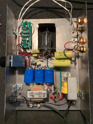
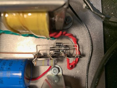
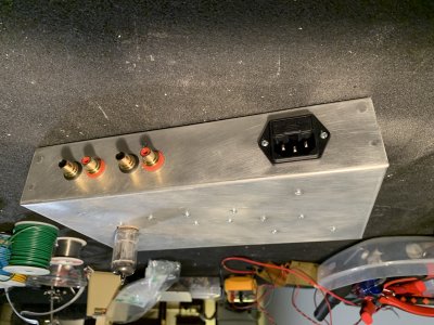
Over the past month I've been ordering parts for the buffer preamp and trying to figure out how to lay it out. Today I managed to finally get the first pass built to a point where I could power it up slowly and take some voltage readings. Pics are attached for reference. So far it's just a chassis plate with front and back pieces to hold the input/outputs and volume . Not sure where it's going to end up, looks-wise.

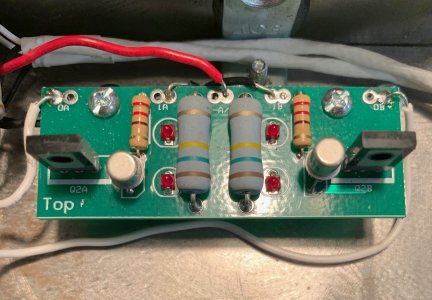
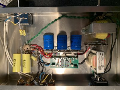
B+ is at 115v with 120v supply. Grids are at 2.18v and cathodes are at 5.8v. Both sets of LEDs on the board fire up.

Right now I have two problems: There's no sound in one (red) channel and the PT is running very hot. The sound out of the channel that's working is pretty good, so that's encouraging at least.

I haven't been able to find any obvious bad connections in the red channel, the input isn't shorted to ground... I'll just have to keep experimenting with that one.

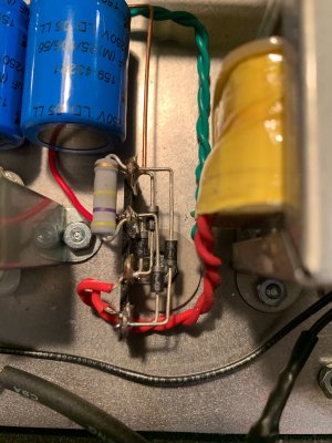
The overheating PT is what I could use suggestions on. The amp is pulling 240mA, and if I'm reading the AES sheet right the max rating for this PT-442 is 315mA so that should be enough headroom. What other readings could I take that might point me in the right direction?

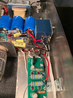
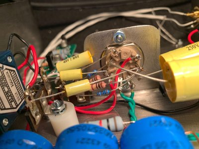
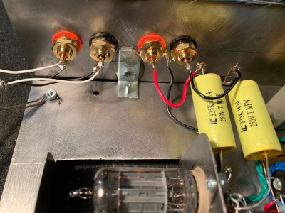
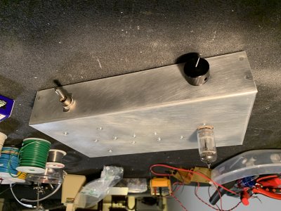
As far as the layout goes, I wanted to try something with the tube horizontal for a lower profile, inputs and outputs on the back, volume knob on the front. Beyond that, I did my best. I was limited to 6" depth because of the steel I could find was a 6" x 18" sheet of 22ga. Seemed to make sense to have the tube in the center with the socked facing inwards for best access to the terminals, and then things just sort of filled in from there. The ground scheme is: Inputs/volume pot/chassis --> CF boards/heater center tap/outputs --> PS Caps --> DC supply negative. It's pretty compact I guess, but too cramped around the terminal strip (that holds all the connections to the B+, two ground lugs, and CF boards and cathodes/grids) and the volume pot. I appreciate any feedback if anything looks way weird or is a no-no. First try at a layout so I expect there'll be a lot to learn from mistakes here.
 

Attachments

  • IMG_0229.jpg
    IMG_0229.jpg
    838.8 KB · Views: 12
  • IMG_1318.jpg
    IMG_1318.jpg
    544.3 KB · Views: 7
  • IMG_4169.jpg
    IMG_4169.jpg
    373.3 KB · Views: 3
  • IMG_5843.jpg
    IMG_5843.jpg
    341.4 KB · Views: 3
  • IMG_7028.jpg
    IMG_7028.jpg
    623.7 KB · Views: 2
Ah, thanks Paul. Bonehead move. I flipped the diode from the B- to AC so that's fixed. Evidence attached.

After the switch the PT is still running very hot. Could I have damaged it with the backwards diode?
 

Attachments

  • IMG_1181.jpg
    IMG_1181.jpg
    124.5 KB · Views: 6
That's somewhat possible.  I would pull the tubes, power up the transformer, then measure the AC voltage of the two windings.  A damaged transformer is very likely to show problematic voltages on the unloaded windings. 
 
With the tube out, the AC voltages are 63v and 10.5, which is obviously not right. Looks like I fried it, so I'll get another one coming from AES.
 
Got the new PT and swapped it in, but it turns out that wasn’t the problem. With the tube in or out, the new one also measures about 65vac and 10.5vac when hooked up to the rectifier bridge. Unhooked, the voltages are normal. Something must be pulling a bunch of current to drag the voltages down, yes? I’ve been over and over the rectifier bridge and I’m sure I have the diodes oriented correctly now.

Looking back through the thread here again I note you said I needed a pair of PN2222 transistors. At the time I skimmed over the fact that that part number is different from the 2N2222As in the original Anticipation upgrade, and I used new 2N2222As with the S.E.X. CS4 board. The specs on the two look the same except the collector current is 1A with the PN2222 but .625A with the 2N222A, but could that be it. Pic of the board attached. Could a damaged rectifier cause this?

Thanks again for all your help. If it's ok for me to seek help elsewhere, including posting the schematic, let me know. I'd love to relieve you of the burden of dealing with my shenanigans since this isn't an actual product you should have to support, but I've been reluctant to post elsewhere out of concerns about distributing proprietary info.
 

Attachments

  • FullSizeRender.jpg
    FullSizeRender.jpg
    1.4 MB · Views: 14
Please do not post our schematics or other IP. It sounds like you may have bad rectifiers.
 
Doc B. said:
Please do not post our schematics or other IP. It sounds like you may have bad rectifiers.

Roger that.

I’ll try replacing the rectifiers.

Without the (single) tube in the socket the main secondary measures about 65vac where it attaches to the rectifier bridge. The heater winding measures 10.5vac at the socket. With the tube in the primary winding starts at about 63vac then falls gradually. I haven’t run it for long enough to see how far it’ll fall but within say 10 seconds it drops to the mid 50s.
 
I've been listening to this for a few weeks now after sorting out this last problem. It sounds great with the KT550 and I'm planning on sticking with it long term. There's still a tiny amount of hum through 96db sensitive speakers, so I'm thinking I'll re-chassis it with a saner layout.

Paul Birkeland said:
If I didn't have to use that PT, I would just run more current.  More voltage doesn't really matter IMO.

If I stepped up to, say, a Hammond 262D6 (12va 120V secondary @ 53 ma), that should keep the voltage in the same range and not require beefing up the PS caps, but though I understand I'd need to lower the value of the R1 to let the CCS draw more current, I'm not sure how to calculate what value needed, and if any changes would be needed in R2 and the bias resistor. Would you be willing to give me any guidance on what those values should be? No worries if not, but no hard in asking.

Thanks again for all the help with this. It's been a great learning experience.
 
The 6.3V heater winding needs a ground reference of some kind, which I didn't draw into the original schematic.  How did you end up dealing with that in your build?  That may be all that's left to get nice and quiet.
 
I just copied the original Foreplay I circuit and so have a 68k resistor in parallel with a .1mfd cap from pin 9 to the same ground point as the CS4. The input/output ground is the only thing "upstream" from that point, and is also the chassis ground.

So do you think I wouldn't see much or any improvement by running more current and moving the load 12AU7 load line up a bit?
 
atalcott said:
So do you think I wouldn't see much or any improvement by running more current and moving the load 12AU7 load line up a bit?
Probably not. 

Your volume pot also works best when mounted to metal and can get noisy if mounted to wood without some kind of connection to bond it to the chassis earth.
 
Alright I’ll leave the PT alone then. Thank you for the feedback.

The volume pot body is grounded to the chassis. This buffer was a separate build from the Foreplay I I posted pics of at the beginning of this thread, and there’s no wood involved in this one. The chassis I made for the buffer is just some cobbled together steel plates and it’s pretty ugly. I want to put it in a proper chassis anyway, so I’ll take the opportunity to revise the layout a bit and in the process track down that last bit of hum.
 
Here she is in the new chassis. It's dead quiet now and sounds great. Calling this project a wrap.

Thanks again for all the help. It's been an awesome learning experience.
 

Attachments

  • IMG_1618.jpg
    IMG_1618.jpg
    2.5 MB · Views: 10
  • IMG_1619.jpg
    IMG_1619.jpg
    2.5 MB · Views: 7
  • IMG_1617.jpg
    IMG_1617.jpg
    2.3 MB · Views: 14
Back
Top