Help with 60Hz hum in Foreplay I in custom chassis

The KT-550 manual rates the input sensitivity at 1v RMS for 50 watt output. The pre-amp that was designed to go with it was the KT-600. Schematic here: http://www.mcmlv.org/Archive/HiFi/LafayetteKT600.pdf.

With everything up and running and no input signal, just the hum present, I'm reading 0.000VAC with my Fluke 115 across the speaker load. With an input signal the voltage varies, naturally. At low-to-moderate volume the peaks look to be about 0.6VAC. At moderately loud the peaks are up to around 1.6VAC.

I will try installing a 3-wire power cord on the power amp in the next couple days. It's been on my to-do list anyway.

The hum is pretty dang quiet, but definitely noticeable in between songs at ~8 ft. from the speakers as I sit here.
 
Just installed the 3-wire cord on the power amp--no difference in the hum. :|

I ordered the attenuators too. We'll see how those do.
 
Alright, while I'm waiting for those attenuators, a little update. I've been reading whatever I can find on grounding and hum issues, including this page 
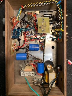
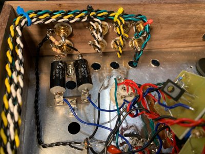
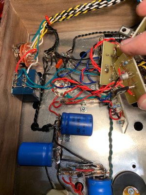
http://cognitivevent.com/av_hum.html, which has some specific info about the Foreplay. I haven't had any big "ah hah" moments about my problem in particular but it's been good to delve more deeply into the principles. I tore down all the ground and signal wiring and rebuilt it based on what I've gathered. Pics attached. The first is a general overview with the VA/CF boards in their normal spots, the second two are closer views of the two sides of the thing with the boards moved out the way.

  • Twisted pairs for the input signal wires, with grounds split off from the signal wires near the source selector switch and attached to a terminal where the volume pot ground is also attached.
  • I debated about where to ground the output jacks, since the original FP has their first ground at the output jack grounds and then on to the volume pots, but I also read in several places that the output jacks should be grounded as close to the cathodes grounds of the first stage as possible. I decided on the latter, so ran a twisted pair from the output jack grounds to another terminal on the same strip. The cathode and heater center tap grounds also go to this terminal.
  • The grounds for the VA/CF boards go to the third terminal on this strip.
  • I then have a 18awg twisted trio from these terminals to the ground of the third filter cap.
  • Shortest possible 18awg wires run from the negative terminals of the second and third filter caps to back to the negative terminal of the first filter cap.
  • I've tried connecting the PS to the chassis at the third filter cap ground, first filter cap ground, and not at all. I've ended up leaving it connected to the third filter cap ground.
  • Lastly, since I've got those attenuators on the way and Mr Joppa mentioned my attenuating resistors possibly affecting the treble, I removed those and the 10ks between output and ground and reinstalled 470k resistors between output and ground.
  • For S&Gs I put rubber washers between the PT and the chassis plate.
  • Also tried adding a .1uF cap with a 10k resistor across it between the third filter cap ground and the chassis, based on the grounding schematic on the page linked above. I confess I don't understand exactly what that's supposed to do, but I had the parts and it seemed worth trying.

I think this all amounts to a star-of-stars type scheme, with all the runs kept as short as they can be, given the configuration.

The result? The hum is about the same as it was before the re-wiring. It's definitely louder than with the attenuating resistors. It's possibly a bit louder in one channel, but it's been like that all along.

But at least my wiring is a bit more respectable now!

I hope the attenuators bring the hum down to an inaudible level, but I'd love to be able to attain a silent build of the circuit without them. This being such an extreme scenario, it seems like an excellent opportunity to fully explore the mysteries of hum and noise.
 

Attachments

  • IMG_0742.jpg
    IMG_0742.jpg
    2.3 MB · Views: 21
  • IMG_0743.jpg
    IMG_0743.jpg
    1.9 MB · Views: 15
  • IMG_0744.jpg
    IMG_0744.jpg
    2.1 MB · Views: 13
Nothing but a shot in the dark: unbolt your choke and move it around while checking the hum. Make sure that you don't zap yourself in the process.
 
Probably not related but the 1k resistor at the HV rectifier looks like it has been toasty, is it shorted across the first filter cap?
 
No luck with moving the choke around. That 1k resistor connected to the HV of the rectifier isn't shorted either. I'll see about replacing it just to be safe. I plan on rebuilding the PS entirely with new parts at some point anyway.

One of the Pauls had asked earlier what VAC I was getting at the speaker terminals. When I tried to measure that earlier I wasn't doing it properly. I have 57.5mVAC on channel A (tube A) and 12mVAC on channel B at the speaker terminals. At the preamp outputs I have 6.5mVAC on channel A and 3.9mVAC on channel B.
 
I made two small changes that seem to have helped a bit. First, I made the connection to ground at the terminal where the output jack and the cathodes attach. I'd read in this article from the Valve Wizard about the chassis connection being as close as possible to the outputs.

Second, noticing the imbalance between channels in the hum voltage, I remembered that I'd replaced the LEDs with newer HLMP-6000s and also had replaced the transistors on the quieter channel (at some point when I was moving things around with the ol' chopstick I had shorted that side out and fried the transistors). I replaced the transistors and LEDs on the noisier channel, and though the hum is still clearly audible, it's about as quiet as it has been. I'm measuring about 12mVAC on both speaker terminals now.
 
The attenuators came yesterday and they did help a ton. The hum is still there with my ear right up against the speaker, but from normal listening distance it’s not audible. I bet the configuration could stand yet another set of -12db attenuators in series. Even with these installed the system is still louder than I’m ever going to listen to it at 1/4 volume. The Foreplay is really just not a good match for KT550, but it still sounds better than my other current option.
 
I would suggest you build just a cathode follower buffer preamp to use with the KT-550.  You could parallel the halves of the 12AU7 to do this.  If you'd like, I could draw something up, it wouldn't be that complicated to adjust your build.  This would reduce your system gain by another 24dB.
 
There's not a ton of HV current available from that little PT, hence the super low operating current, but this will work much better with your system.
 

Attachments

  • buff 1.jpg
    buff 1.jpg
    413.5 KB · Views: 35
Thanks Paul. Everything else is perfectly clear but I haven’t seen than overlapping circle symbol before and am confused there. My best guess is that they just represent the existing transistor/LED network, and the resistors on the board need to be adjusted to the values listed? Am I in the ballpark? I take it the “3mA” is the “super low operating current” you refer to.
If you weren’t tied to the original PT how would you adjust the power supply to bump that up, and what advantages would that provide?
 
atalcott said:
overlapping circle symbol

Constant current source. In this case, the C4S: Camille Cascode Constant Current Source.

cheers, Derek
 
atalcott said:
Thanks Paul. Everything else is perfectly clear but I haven’t seen than overlapping circle symbol before and am confused there. My best guess is that they just represent the existing transistor/LED network, and the resistors on the board need to be adjusted to the values listed? Am I in the ballpark? I take it the “3mA” is the “super low operating current” you refer to.
If you weren’t tied to the original PT how would you adjust the power supply to bump that up, and what advantages would that provide?
That is the CF white board that would come with the anticipation.  The VA boards are not used. 

If I didn't have to use that PT, I would just run more current.  More voltage doesn't really matter IMO.
 
Paul Birkeland said:
That is the CF white board that would come with the anticipation.  The VA boards are not used. 

If I didn't have to use that PT, I would just run more current.  More voltage doesn't really matter IMO.

Got it. Still not totally clear on the changes around the CF board though. Currently R2 on the boards is connected to the B+ on one side via the "C" lead, and to the gate of the MJE340 and the anode of the first LED on the other side. In your schematic there appear to be just two connections to the CF board now, with the new grid leak resistor R1k connected to the MJE340 source along with the cathode (after the new bias resistor Rbias). But that would take R2 out of the circuit, and your schematic also indicates a change in R2 from 100k to 150k, so obviously that doesn't work. If R2 were connected to R1k via lead "C" then I wouldn't think R2 would need to be 2w, since it's just ultimately connected to the grid... Schematic of the CF board attached so you don't need to look it up.

I'm thinking about building this as a separate unit since 1) seems like a shame to use both tubes when only one is needed, 2) I don't really need source selection and could make it that much more compact, and 3) I have my eye on an SE KT120 build down the road that actually needs a high-gain preamp like the Foreplay.
 

Attachments

  • IMG_5911.jpg
    IMG_5911.jpg
    509.9 KB · Views: 17
I didn't draw the connection from the C4S to B+, but that does need to be made.  R2 connects to B+, just as it does in the original Foreplay Anticipation upgrade.

The new grid leak resistor (rlk, which is 1,000,000 ohms, not 1K) and the 1K rbias connect to the collector of the MJE340, which is the easiest pad to identify on the board.

The B+ connection is easily identified because it will only have the free end of R2 connected to it.

The ground connection is the other connection that feeds the smaller R1 and feeds the 2N2222 transistor.
 
Great, that all makes sense, thanks. If I build this as a separate unit, would any of the PCBs for the newer CCS upgrade kits work? If so, can I buy those separately?
 
You could use the SEX 3.0 C4S upgrade.  The LEDs need to be turned around and you'd need a pair of PN2222 and a pair of MJE340 transistors.
 
Back
Top