Help needed to stop blowing fuses

PassionForSound

New member
Hi all,

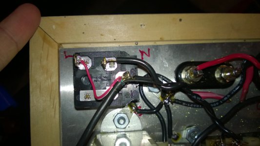
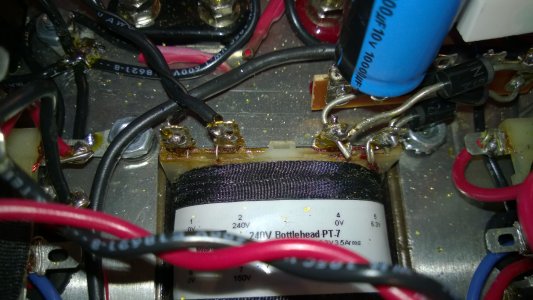
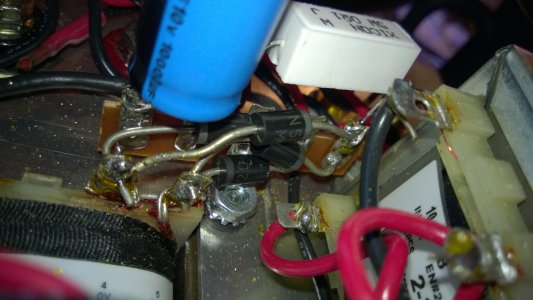
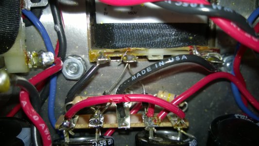
I'm currently trying to salvage a bit of a mess. A friend of mine tried to build a SEX, but has made a bit of a hash of it (no offense intended to him).

After rebuilding the obvious issues, I've tested the resistance and everything is ok, but the SEX keeps blowing fuses. I've tried testing for shorts in the power circuit, and the first thing I'm wondering is if (testing from the main earth near the power inlet) 0.4 ohms at the transformer terminals 4 and 5 is my issue.

Any other suggestions for tracing a fuse-blowing short when all resistance checks are fine and there are no visual signs of shorts?
 
Is it instantly blowing when you try to power up?  Do you see the heaters starting to glow?

.4 ohms is so low it doesn't sound like the issue to me, but i might be wrong.  What do 1 & 2 read?

As usual post some close up pics if you can, fresh set of eyes might spot something...
 
Thanks Jamie.

Terminals 1 & 2 have infinite resistance measured from T23.

The fuses blow instantly with no sign of glow from the tubes.

Should there be something lower than infinite resistance between transformer terminals 6&7 and either transformer terminal 1/2? I'm wondering if the transformer was buggered during initial power up.

Here are some picks. Sorry about the mess - I'm trying (in vain) to clean up as much as I can without a full rebuild.


Attachments

  • WP_20140503_16_35_06_Pro.jpg
    WP_20140503_16_35_06_Pro.jpg
    1.8 MB · Views: 132
  • WP_20140503_16_35_13_Pro.jpg
    WP_20140503_16_35_13_Pro.jpg
    2.1 MB · Views: 124
  • WP_20140503_16_35_21_Pro.jpg
    WP_20140503_16_35_21_Pro.jpg
    1.9 MB · Views: 118
  • WP_20140503_16_35_38_Pro.jpg
    WP_20140503_16_35_38_Pro.jpg
    2.1 MB · Views: 122
Sorry, going back to your original post, i assumed when you said terminals 4 & 5 you were talking about the heater supply not the high voltage supply. The HV supply terminals should give you a very high reading and changing as the caps charge from the meter. From my notes i was seeing over 100k and counting so .4ohms is certainly not right. I dont see anything obvious in the attached pic, can you post a few more from further down the power supply trail..

Also double check the heater diodes, one of them i cant really see but the leads for the two going to terminal C5 look very close together, just make sure none of them are contacting each other.

Are you 100% the rest of your resistance measurements are within spec?

P.S. I'm Mark, Jamie is the other one who posts too much :P
 
The filament winding (terminals 4 and 5 of the power transformer) are grounded, so those measurements are fine.

The first thing to check is the DC resistance at the power cord. You should see infinite resistance with the power switch Off, and around 10 ohms with it On. If you pass this test, then you can eliminate the input power wiring and the power transformer primary. If you don't pass this test, then stop here and we'll help you trace the fault in the primary power wiring.

Once you've confirmed the primary wiring as above, and if you have not tested it without tubes, do so now. I assume you have a stock of spare fuses, we may go through a few in this process! If the fuse still blows then there is a problem in the power supplies; if the fuse does not blow then the power supplies are not at fault.

I think it would just make this post confusing to offer next steps, because they depend too much on the results of the above tests. Report back and we'll keep working!
 
mcandmar said:
Sorry, going back to your original post, i assumed when you said terminals 4 & 5 you were talking about the heater supply not the high voltage supply. The HV supply terminals should give you a very high reading and changing as the caps charge from the meter. From my notes i was seeing over 100k and counting so .4ohms is certainly not right. I dont see anything obvious in the attached pic, can you post a few more from further down the power supply trail..

Also double check the heater diodes, one of them i cant really see but the leads for the two going to terminal C5 look very close together, just make sure none of them are contacting each other.

Are you 100% the rest of your resistance measurements are within spec?

P.S. I'm Mark, Jamie is the other one who posts too much :P

LOL. Sorry, Mark! I do know the difference between you and Jamie, but I think in my tired state and having had so many great discussions with you both about caps and attenuators, the two of you temporarily became one in my mind.  ???

I checked the diodes after my post because I was wary of them too, but all is clear despite being close. I've moved them a little to create more space as well.

All other resistance checks are 100% within spec.
 
Paul Joppa said:
The filament winding (terminals 4 and 5 of the power transformer) are grounded, so those measurements are fine.

The first thing to check is the DC resistance at the power cord. You should see infinite resistance with the power switch Off, and around 10 ohms with it On. If you pass this test, then you can eliminate the input power wiring and the power transformer primary. If you don't pass this test, then stop here and we'll help you trace the fault in the primary power wiring.

Once you've confirmed the primary wiring as above, and if you have not tested it without tubes, do so now. I assume you have a stock of spare fuses, we may go through a few in this process! If the fuse still blows then there is a problem in the power supplies; if the fuse does not blow then the power supplies are not at fault.

I think it would just make this post confusing to offer next steps, because they depend too much on the results of the above tests. Report back and we'll keep working!

Thanks Paul. I have plenty of fuses (1A quick blow - is that ok?)

I've tried testing the power socket this morning, but not sure if I'm doing it right so I'll share my process:

1. With switch off I measured resistance between earth (chassis screw) and the three pins in the power socket. Readings are E: <0.5ohms, L: infinite, N: infinite

2. With switch on the same readings create the exact same results. Is this the issue?

Notes: no connection to the power cable and mains outlet for this test. A fresh fuse was installed and intact.
 
Those readings are correct, as you're measuring with reference to ground.
What you want to measure, with the unit unplugged, is between L and N: OL with switch off, & around 10 ohms with the switch on.
 
Then you are good on the primary side of the transformer.  The problem must exist on the secondary side. 

I don't know if it has been mentioned, but backward caps can blow the fuse.
 
I've checked a lot of the caps, but I can't promise that I've checked all of them. One of the biggest issues with this build is the fact that many items were installed with incorrect alignment so there's a strong chance that there's a cap causing the grief. I'll check and report back.

In the meantime, what should I measure next?

So far I've checked the Schottky rectifiers and all are reading as though they're undamaged and I've confirmed that they're correctly oriented. I have tested for shorts to earth along the various power lines (6.3V heater power and main power), but not sure if I should be looking for something other than a short to earth.
 
Is the stock fuse with the S.E.X. fast or slow acting? I have the fuse that's in my personal S.E.X. but I thought they were fast fuses that are provided.
 
OK. Tested with a slow blow fuse with no joy, but it allowed me to here an electronic sound which seemed to come from the tube socket nearest the HP jack.

There was a lot of excess solder on the socket pins prior to my efforts to suck away as much as possible and I noticed that the tube doesn't seat properly in that socket (it sits about 1-2mm off the chassis plate). I'm wondering now if there's some arcing or something going on in the socket. Would that cause excess current flow?

The good news is the tube is still fine (especially because I'm testing with my own tubes because he didn't have his handy), but I can't see any visual clues of where the problem lies and I'm not exactly sure what I should be testing for.

Paul, I just re-read your post and realised you are suggesting powering up without the tubes installed. I'll try that when I get back home after a short errand and get back to you.
 
No tubes. Blown fuse.

This time I used a quick blow fuse so I couldn't hear any noises, but with no tubes installed there is still a very definite problem. There is a visible layer of flux on the ceramic between A1 and A8, but no solder and 280k ohms so I don't think that's the issue.
 
Great! Now we know it's not the tubes or the primary circuit, so it must be one of the power supplies.

It is not that uncommon for a bit of solder to wick down into a tube socket pin, blocking the tube from fully entering, so your approach of sucking as much of the excess out as possible is a good one. Pay special attention to pins 7 and 8; they are the heater and if they are shorted together that will indeed blow the fuse. Also, since it's happened a few times, make sure the sockets are correctly oriented with the notch at the center towards the power transformer. A few people have mounted them 180 degrees rotated by accident!

That said, if you don't see the problem there I'd test the high voltage first, just because it's easiest:

There is a single wire at power transformer terminal 6. Disconnect it temporarily; this will disable the high voltage power supply. If it still blow fuses then the problem is in the filament power supply or wiring. If not then we'll look into the HV supply.
 
Thanks Paul.

I disconnected the black wire from transformer terminal 6 (it connects to terminal strip contact #1 at the other end). Still blowing fuses so the issue is obviously in the heater circuit.

I've fully rebuilt the C1-5 terminal strip since the amp started blowing fuses so I'm confident the fault isn't on these contacts, but could be a faulty diode or could be at the other end of one of the connections coming from C1-5.

I'm guessing I should disconnect the heater wire next to isolate C1-5 from the tubes?
 
Back
Top