Help needed to stop blowing fuses

Disconnected heater wire from C1 & C2. Still no joy.

I'm going to do another visual inspection for shorts. I have tested the diodes in situ, but not sure if I need to remove them for accurate testing. I'll await your guidance with my sincere thanks.
 
Sorry for the multiple posts - I'm trying to cover as much as possible to minimise delays due to our time zone differences.

I decided to remove and test the capacitor from C1-2 in case it was blown during initial attempts to power up, but it tests the same as a new one using the diode function on my meter (i.e. counter climbs gradually to about 1500 before reading infinite)
 
Wow - you've done some good guessing!

If I am reading your posts right, it is now down to the heater winding on the transformer and the recifiers/resistor/capacitor.

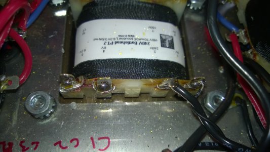
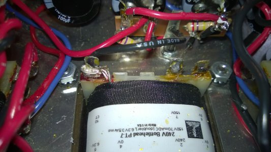
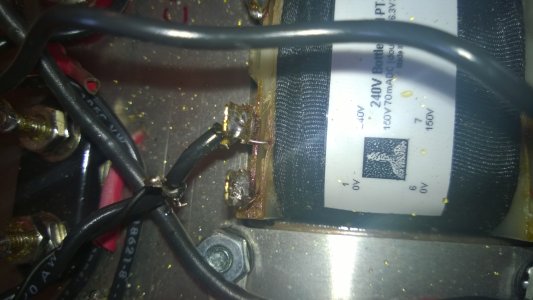
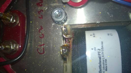
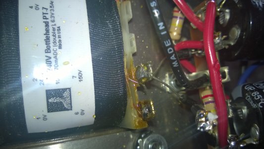
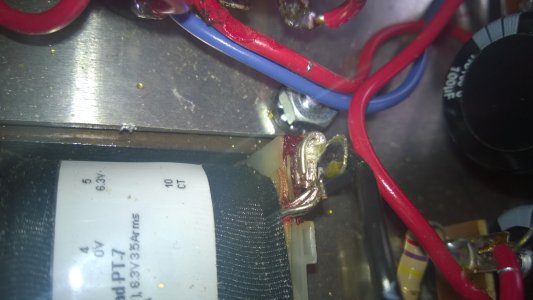
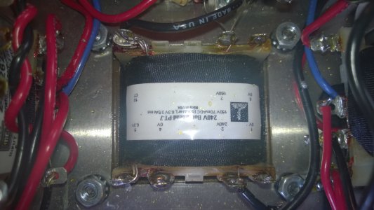
I'm sorry to say this because it will be a pain, but you should remove the diodes from one of the transformer terminals, 4 or 5. If I were you I would remove the from both and unbolt the power supply terminal strip. Then see if you can blow the fuse - it is extremely unlikely that the transformer winding is internally shorted, but we need to be sure. At this point, only the transformer primary (which you have already confirmed is correctly connected) is connected. In the unlikely event that the fuse still blows, the transformer is suspect - but that winding is only 0.095 ohms and you probably can't measure the difference between that and a lower resistance.

Assuming you do NOT blow the fuse this time, then the power supply that you pulled off, and probably have in your hand, is somehow shorted or incorrectly wired or has bad components. I can't see enough in the pictures to tell what is going on, and you may find that a bright light, magnifying glass, and a lot of patience is needed even if you have it in your hand. But that's why I suggested removing it all.

Again, if it were in the Bottlehead lab and my job was to fix it, I would just throw is away and build a new one. But you would have to request and wait for the parts, so make your own judgement about how much time to spend puzzling it out.
 
Wow there isn't much left now.  Just a thought, double check the black jumper wire on terminals C1 to C4 in case its on the wrong terminals.
 
Thanks Paul. I'll do that now and maybe rebuild the C1-5 strip yet again. I have all new components (some of which I have used in the current setup depending on the visual state of the old components. I'll use all fresh components this time around.

Mark, thanks for mentioning the jumper because I don't know if there is one!? But I'm not near the amp to check so it might just be my memory - I'll go looking specifically.
 
Mark, I might owe you a beer! Just checked and the C1-C4 jumper is missing. I noticed that nothing was connected to the capacitor at C1 when I removed it for testing, but was so focussed on testing it that I forgot to check the manual to see if it was somehow correct.

I'll add the jumper and test as soon as I can. Could that have caused the blown fuses do you think?
 
Culprit found. The transformer itself is the issue  :(

I'm assuming this means a replacement is required?

I'm attaching photos of the exact configuration when the transformer blew the last fuse (and also made an obvious, but very brief buzzing sound)
 

Attachments

  • WP_20140505_15_48_01_Pro.jpg
    WP_20140505_15_48_01_Pro.jpg
    2 MB · Views: 131
  • WP_20140505_15_47_56_Pro.jpg
    WP_20140505_15_47_56_Pro.jpg
    2 MB · Views: 125
Further to last post. Visual inspection shows no signs of shorting with excess solder, etc. Could this issue have been caused by powering up in the original, faulty configuration? Or could it be caused by excess heat applied to the transformer? There's no signs of heat damage to the plastic at the base of the terminals, but I'm trying to work out what to tell my friend. "It's busted and we don't know why" is always an option, but it'd be nice to let him know some semblance of the cause of his troubles and if he has to buy a new transformer (i.e. if it's not considered a random product fault) it'd help to explain what he did wrong.
 
Contact Eileen for a replacement transformer. Tell her that PJ says it was bad from the start.

Looking at your most recent photograph, I see three wires on terminal 5 and one on terminal 4. There should have been two on each. It's a manufacturing error - the first time I've seen this.
 
I'm sorry, I don't think we can deduce that from the photos. Looking at the shelf full of PT-7s we have, there is an extra turn of one of the two wires attached to terminal 5, and that could be what we are seeing in the photo. I'm late the party, but has anyone suggested measuring the resistance of the primary and secondaries now that you have them all disconnected from the circuit?
 
Start by making sure all the wires are disconnected from the power transformer. First check for shorts between windings.

For the primary to high voltage secondary measure the resistance from power transformer terminal 1 to terminal 6 - should be infinite.

Primary to heater secondary measure from 1 to 4 - should be infinite

high voltage secondary to heater secondary measure from 6 to 10 - should be infinite

Now check the DCR of each winding. I will give you what I measure, your numbers may be a little different.

Primary (1 to 2) 36.8 ohms

High voltage secondary (6 to 7) 40.8 ohms

The heater secondary will be too low a resistance to measure above 0 ohms with pretty much any regular meter and this is why PJ didn't suggest it for the heater secondary. So - and again I'm not sure if this has already been covered - check very closely what PJ suggested, make sure that you have two wires coming out from under the coil wrapper to each of terminals 4 and 5, not three wires to one of them and one wire to the other. If you could take a photo from directly over the terminals it could help us to help you verify the wire count. I'm not saying it's impossible for the transformer to have been mis-terminated in production. We went through our entire stock this morning from two different production batches and we didn't find any here that were mis-terminated. So we can certainly send a replacement with a high degree of confidence if the one you are working with was miswired.

It is also possible that there could be a short in the IEC socket wires coming from the socket to the transformer. I see a fair amount of melted wire insulation on that build, and it might be worth comparing the build with the assembly manual photos of the power switch and power entry wiring on pages 23 and 24.
 
Thanks Doc. I'll do all that and report back.

I do believe there has been excess heat and excess solder applied at various times during the initial build. I've replaced anything that I can that looks too far gone and have tested the IEC socket for shorts with no issues found.

I'll do all the testing, take notes and report back soon.

Thanks again for your help everyone - I feel like this poor kit was cursed from the outset!
 
Doc B. said:
Start by making sure all the wires are disconnected from the power transformer. First check for shorts between windings.

For the primary to high voltage secondary measure the resistance from power transformer terminal 1 to terminal 6 - should be infinite. Infinite 

Primary to heater secondary measure from 1 to 4 - should be infinite Infinite

high voltage secondary to heater secondary measure from 6 to 10 - should be infinite Infinite

Now check the DCR of each winding. I will give you what I measure, your numbers may be a little different.

Primary (1 to 2) 36.8 ohms 9.5 ohms
High voltage secondary (6 to 7) 40.8 ohms 40.9 ohms

The heater secondary will be too low a resistance to measure above 0 ohms with pretty much any regular meter and this is why PJ didn't suggest it for the heater secondary. So - and again I'm not sure if this has already been covered - check very closely what PJ suggested, make sure that you have two wires coming out from under the coil wrapper to each of terminals 4 and 5, not three wires to one of them and one wire to the other. If you could take a photo from directly over the terminals it could help us to help you verify the wire count. I'm not saying it's impossible for the transformer to have been mis-terminated in production. We went through our entire stock this morning from two different production batches and we didn't find any here that were mis-terminated. So we can certainly send a replacement with a high degree of confidence if the one you are working with was miswired.

It is also possible that there could be a short in the IEC socket wires coming from the socket to the transformer. I see a fair amount of melted wire insulation on that build, and it might be worth comparing the build with the assembly manual photos of the power switch and power entry wiring on pages 23 and 24.

The transformer terminals are attached with the following:

T1: 1 thin wire
T2: 1 thin wire
T4: 2 thick wires (I believe - hard to see clearly)
T5: 2 thick wires
T6: 1 thin wire
T7: 1 thin wire
T10: 4 thick wires

The following photos will hopefully show what I am seeing. I've taken them in order from terminal 1 to terminal 10 with a full shot at the end.
 

Attachments

  • WP_20140506_13_19_25_Pro.jpg
    WP_20140506_13_19_25_Pro.jpg
    1.8 MB · Views: 109
  • WP_20140506_13_19_37_Pro.jpg
    WP_20140506_13_19_37_Pro.jpg
    1.8 MB · Views: 137
  • WP_20140506_13_19_48_Pro.jpg
    WP_20140506_13_19_48_Pro.jpg
    1.9 MB · Views: 112
  • WP_20140506_13_19_56_Pro.jpg
    WP_20140506_13_19_56_Pro.jpg
    1.8 MB · Views: 112
  • WP_20140506_13_27_15_Pro.jpg
    WP_20140506_13_27_15_Pro.jpg
    2 MB · Views: 125
Once again, Doc gets to keep the corner office!

No idea what the problem is at this point. The measureable windings are fine, the unmeasureable one looks fine, the primary wi..

wait a minute. 10 ohm primary? That's a 120v PT-7, not a 240v as shown on the label. Crap, we should have seen that a lot earlier!
 
Paul Joppa said:
Once again, Doc gets to keep the corner office!

No idea what the problem is at this point. The measureable windings are fine, the unmeasureable one looks fine, the primary wi..

wait a minute. 10 ohm primary? That's a 120v PT-7, not a 240v as shown on the label. Crap, we should have seen that a lot earlier!

Oh, so it's a mis-labelled US power transformer? (Just checking I'm unsderstanding correctly)
 
Yup, that is what Paul indicated.  Somehow I would expect the 240V transformer primary to be a higher resistance, and impedance.
 
IMO, this info should be some sort of sticky note or part of FAQ, so that in the future everyone can easily determine whether a transformer received with the kit is the correct one or not... Just my 2 cents.
 
Back
Top