Driver testing failure

Jamus

New member
I'm close to finishing my Kaiju build but I'm having a problem at the driver testing stage.

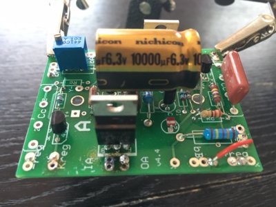
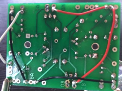
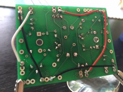
IA and OA on the D socket board were spot on spec. However the voltage at 46U measures 130VDC and the trim potentiometer does not work at changing the voltage at all. For what it's worth the A side worked no problem.

I'm wondering if the fact that turning the screw on the trim potentiometer doesn't change voltage does that indicate that the potentiometer is faulty?

Thanks,
Jamus
 
Jamus said:
I'm wondering if the fact that turning the screw on the trim potentiometer doesn't change voltage does that indicate that the potentiometer is faulty?
This is very, very unlikely. 

There's a set of pads that says Kreg on the A side, what voltage do you get here?  Are you 100% sure that you have TL431's where they should be an PN2907's where they should be?  Are the PN2907's facing the right way? 

What voltages do you get at OA and IB?
 
You could measure across the outer pins of the pot and see if resistance changes as you turn the screw.
 
Caucasian Blackplate said:
This is very, very unlikely. 

There's a set of pads that says Kreg on the A side, what voltage do you get here?  Are you 100% sure that you have TL431's where they should be an PN2907's where they should be?  Are the PN2907's facing the right way? 

What voltages do you get at OA and IB?

Kreg is 3.6VDC on A side, 2.4 on D side
OA and IB are both 300VDC on A, 299 on D
Doubled checked all transistors are in the correct position.
 
Doc B. said:
You could measure across the outer pins of the pot and see if resistance changes as you turn the screw.

Just checked and the resistance does change after turning the screw, but not the voltage

*edited for clarity
 
Excellent data, very helpful. R3 may not be soldered well.

The pot is configured as a variable resistor, and makes a voltage divider together with R3. The divided voltage is compared with the internal 2.5v reference. If the R3 leg is not connected then the adjusted voltage is stuck at 2.5v, which would give the observed 130 volts.
 
I touched up R3 and all the other terminals for that matter but no changes in voltage at 46u.
Then I screwed something up big time. I was remeasuring IA one OA and the multimeter lead must have touched both terminals. Loud pop, bright flash, now I get no reading at OA. How bad did I eff this up? :'(
 
You probably took out the 2N2907 and the MJE5731. Do the LEDS look exploded?
 
LEDs look okay. So I'll replace the PN2907s and MJEs. Anything else to replace based on the initial problem?
 
When you get the transistors replaced, I would recommend posting some photos of the offending board, both top and bottom sides if at all possible.

You may also have a jumper in the TL431/trim pot part of the circuit that isn't where it should be.

-PB
 
Getting back to the original issue. I had exactly the same thing happen today with a Paramount, which has the same circuit. I had built a replacement board for the 5670 and the tube was stuck at 130V no matter how the trimmer was set. Closer inspection showed I had completely missed installing the 4.99K resistor that is in series with the trimmer. Installed it and it worked perfectly.
 
I replaced the MEJs and PN2907s but I still get 0 VDC at OA and the B side LEDs don't light up. Here are several photos of the board. I tried to get it from different angles but let me know if you need better pictures. Note the damage between IA and OA  :'(
 

Attachments

  • IMG_3160.JPG
    IMG_3160.JPG
    126.8 KB · Views: 98
  • IMG_3161.JPG
    IMG_3161.JPG
    114.5 KB · Views: 100
  • IMG_3162.JPG
    IMG_3162.JPG
    116.2 KB · Views: 86
  • IMG_3163.JPG
    IMG_3163.JPG
    104 KB · Views: 81
  • IMG_3164.JPG
    IMG_3164.JPG
    116.8 KB · Views: 85
  • IMG_3165.JPG
    IMG_3165.JPG
    112.3 KB · Views: 89
Well, I was hoping someone more knowledgeable might wade into these waters, but since it's been quiet I'll take a stab.

First of all, your symptoms seem to be 0V at OA, but the LEDs are lighting up on this side. Is that correct?

The cause that makes the most sense is a dodgy solder joint. From your pictures, it looks like some of your joints weren't heated long enough for the solder to properly flow. For instance, look at the rightmost hole of bA in IMG_3161. The wire can be seen coming up through the hole with solder on it, but the pad looks untouched by solder. This is just one example, this issue is seen on several terminals.
Solder needs to get to its liquid state and stay there long enough that to seep onto whatever the metal surfaces, which need to be hot enough to allow that. The pins of the A side 5731 are hard to make out in the photos (the Bside is clearly blobby (the other sign of not enough heat)), but they would be highly suspect for your symptoms.

The other cause that could be an issue is a fried Zener. Test your diodes by measuring the resistance both ways across each diode. One way should read very high (in the high KΩ or MΩ), and the other way should read over limit.
 
Yes, check the zener diode string. If it is shorted the voltage at OA will be pulled down.
 
Doc B. said:
Yes, check the zener diode string. If it is shorted the voltage at OA will be pulled down.

Unfortunately you are correct, all Zeners on that side are 0 ohms. I really wish I could take back that momentary lapse in hand eye coordination that kicked off this shitshow!

I was just telling my wife how I would be sad when this build was done because I really enjoy building these kits. I guess the gods were listening and gave me some bonus rebuilding time!

So I'll order 5 new Zeners and touch up that board (thank you Josh for the thorough look at the photos too by the way). I'll report back when that is done.

Thanks!
Jamus
 
OK, glad you found the problem. That string is not too terrible to replace. Once it is back together the behavior should be that upon startup OA immediately goes to about 350V. That's what the zener strings regulates the voltage to. Then as the 5670 heater warms up the shunt regulator kicks in a pulls it down a bit to about 300V. That way the zener string drops out and thus has no negative influence on the sound. PJ is pretty tricky sometimes.
 
You are also more than welcome to test the amp without the zeners in place.  They are a preventative measure that protects your amp from 5670 tube failure.
 
I replaced the Zeners today. Interestingly one of them was split in two right through the body. After replacing those the voltage is good everywhere except for 46U.

I usually use a pencil tip style solder iron tip which doesn't transfer heat as well but is good in small spaces like the PC board. I switched to a broader tip and reflowed all the joints on the board to eliminate any blobs. Still, I get the same 130V at 46U.
 
***SEE LATER POST*** I'm leaving this as posted but lined out. The reference to pin 2 should be pin 8 of the D socket.

What is the DC resistance from the 5670 pin 2 to ground? This is a test of the R3 issue mentioned (not very clearly) earlier by myself, PB, and Doc B. It should be between 5000 and 15000 ohms, and it should change as you adjust the trim pot.
 
Back
Top