Driver Testing error (RESOLVED)

At this point it would be super helpful to trade the PC boards between sides.  If the OA voltage stays on the same socket, then we need to figure out what's going on with the socket wiring itself.  If the OA voltage moves with the board, then there's something wrong with the PC board population/jumpering that just hasn't been noticed yet.
 
I switched the boards and the issue remained with the board. The OA was still 145 VDC on the board that was previously on the D side and now moved to the A side. I've attached photos of the two boards. The problem board is on the left in both photos.
 

Attachments

  • PXL_20230202_205837996 v2.jpg
    PXL_20230202_205837996 v2.jpg
    1 MB · Views: 23
  • PXL_20230202_205344561 v2.jpg
    PXL_20230202_205344561 v2.jpg
    975.5 KB · Views: 16
Hard to tell from picture, but the black wire going from bA to -reg has a long bare area at bA.  Could this be touching one of the pads on the pot especially when the wires are compressed when attaching the board?

It's a long shot


Debra
 
I would set your meter to continuity beep and be sure none of the legs of Q1 on the A side of the funky board are touching.  It's possible you may have a teeny tiny solder bridge causing problems there.
 
Underside pic - right hand board - looks like a cold joint on a 431 pad. The row of pads above IB, fifth pad in from right.

Topside pic - left hand board - possibly a cold/missed connection at the bA pads next to the blue trimpot. Though it seems to look OK on the underside. I'd reheat just to be sure.
 
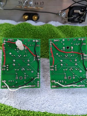
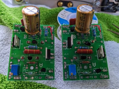
Thank you all for the suggestions. I replaced the black wire from ba to -reg, repositioned and resoldered the red wire from +reg to IB, replaced the B side R1, and fluxed and resoldered several of the very close soldering points to ensure they weren't touching. I was having some difficulty measuring the B side 431, so I also replaced that again. Paul, you're right about the square pad for the D2 (good eye), I lost it when desoldering an earlier blow out of 90R9F that resulted in blown diodes. The diode seemed to operate OK, so I moved on, but maybe that explains my issues.

Anyway, after all that I turned on the power and still got the ~145 VDC on OA. I left the system on for a bit to perform some testing and then, while not probing the board or components, the 90R9F blew out again. At this point I'm thinking I'll start afresh with a new board and components because simply replacing that 90R9f and affected components might just put me back to square one in trying to locate the ~145 VDC on OA issue. Also, there's enough damage to the board at this point that starting anew is probably the way to go.

 
Thank you all for your help. My Kaiju is now up and running and sounding great.

I received the new board and components, built up the new board, installed it, and I was initially getting low readings on OA at about ~13 VDC, so I replaced the zener chain and after that the numbers were looking perfect. I put last touches on it today and placed it into my system and it's sounding great.
 
Back
Top