Loggie
New member
After having finished my Crack (a thread about that is stil to come) I decided to upgrade the standard pot with a 41 stepped series attenuator.
I stumbled on the "41 stepper" after Googling for a stepped attenuator and was initially going for a 23 stepped one.
However the "41" caught my attention")
Also more steps would give me a better control.
This attenuator is made by (or made for) Acoustic Dimension in The Netherlands.
It comes in a few variations:
http://www.acoustic-dimension.com/attenuators/attenuators-main.htm
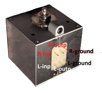
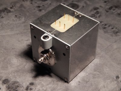
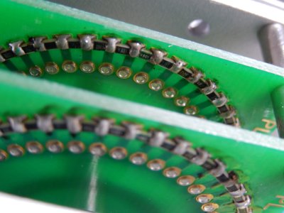
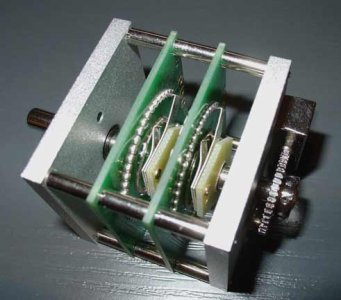
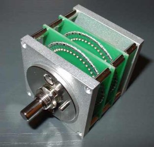
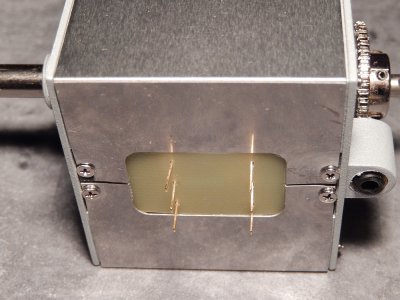
As shown on the pictures below you can see that the resistance is achieved by using 2x41 SMD resistors.
Peter the owner of Acoustic Dimension is a pleasure doing business with.
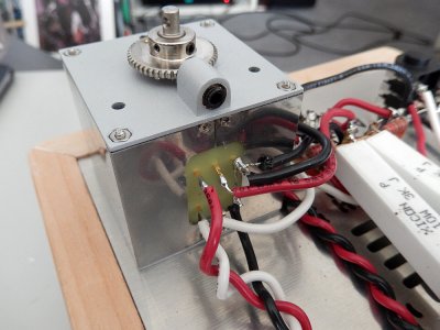
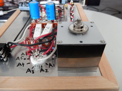
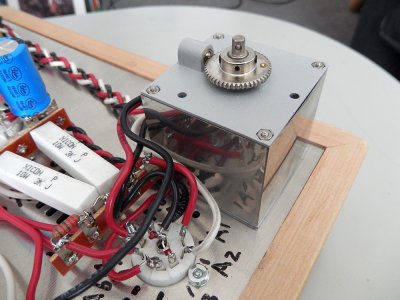
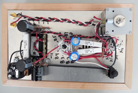
At first I was afraid it might not fit but after making the original hole slightly bigger it fitted (very tight fit.....see pictures).
The attenuator works like a charm and sounds great.
I measured both the original pot and the 41 stepped one......the original had a 1% inbalance between channels, the 41 stepper none.
Now I only hope that the Speedball upgrade I ordered will still fit ;D
Here are some pictures:
Update: Added 2 pictures (from the internet) that show the inside, also visible the 2x41 SMD resistors.
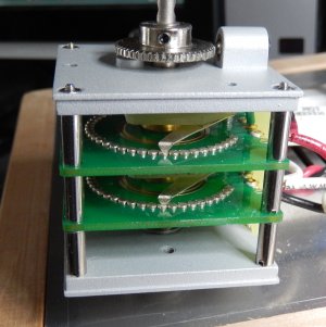
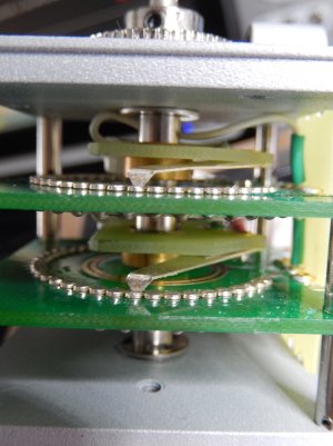
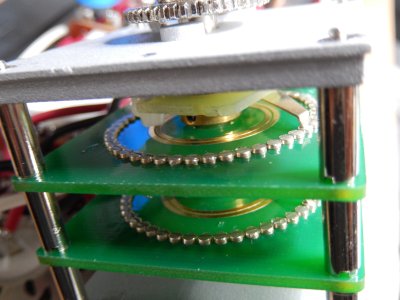
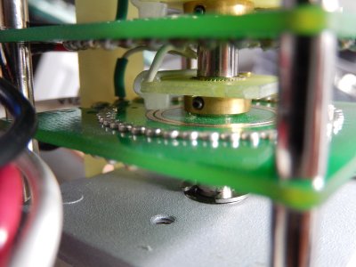
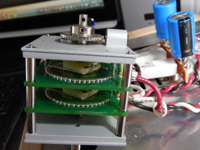
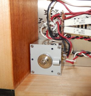
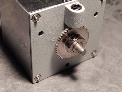
Update2: Removed the casing from the attenuator and made some photo's to show the inside and working.
I stumbled on the "41 stepper" after Googling for a stepped attenuator and was initially going for a 23 stepped one.
However the "41" caught my attention
Also more steps would give me a better control.
This attenuator is made by (or made for) Acoustic Dimension in The Netherlands.
It comes in a few variations:
http://www.acoustic-dimension.com/attenuators/attenuators-main.htm
As shown on the pictures below you can see that the resistance is achieved by using 2x41 SMD resistors.
Peter the owner of Acoustic Dimension is a pleasure doing business with.
At first I was afraid it might not fit but after making the original hole slightly bigger it fitted (very tight fit.....see pictures).
The attenuator works like a charm and sounds great.
I measured both the original pot and the 41 stepped one......the original had a 1% inbalance between channels, the 41 stepper none.
Now I only hope that the Speedball upgrade I ordered will still fit ;D
Here are some pictures:
Update: Added 2 pictures (from the internet) that show the inside, also visible the 2x41 SMD resistors.
Update2: Removed the casing from the attenuator and made some photo's to show the inside and working.
Attachments
-
 acoustical dimension-41 stepped attenuator series-1.jpg577.3 KB · Views: 365
 -
 Opposite SMD res..jpg1.3 MB · Views: 278
 -
 inside mechanism-4.jpg2.8 MB · Views: 209
 -
 inside mechanism-3.jpg1.6 MB · Views: 211
 -
 inside mechanism-2.jpg1.8 MB · Views: 224
 -
 inside mechanism.jpg306.6 KB · Views: 194
 -
 41Stepped-inside ring with SMD res.-1.jpg1.8 MB · Views: 245
 -
 41stepped-inside-smd-2.jpg21.9 KB · Views: 222
 -
 41stepped-inside-smd-1.jpg16.4 KB · Views: 330
 -
 Past net-6.jpg553 KB · Views: 241
 -
 Past net-5.jpg589.3 KB · Views: 226
 -
 Past net-4.jpg600.1 KB · Views: 272
 -
 Past net-3.jpg587.3 KB · Views: 334
 -
 Past net-1.jpg841.3 KB · Views: 392
 -
 acoustical dimension-41 stepped attenuator series-3.jpg558.6 KB · Views: 303
 -
 acoustical dimension-41 stepped attenuator series-2.jpg575 KB · Views: 285
 Thanks for help.