Crack & Speedball -Wrong resistance and Voltage readings

alesi

New member
Hi,
after 4 years in the box I "managed" to assemble the crack incl. speedball update.
The first attempt was also my first attempt in soldering so I expected some hick-ups. I got a bit overexcited and without the right resistence readings I plugged it in to test the voltage. Tube started glowing, but unfortunately there was also some smoke coming from the region T12-T14, not sure whether it was the capacitor or the wirebound resistor underneath. I realised the the powder coating might be the culprit, next to my soldering skills. I desoldered everything (!) and started from scratch. This time I dremelled all points that required ground (ground lug, T3, T8). Looking at the resistance and voltage readings I always measure a 0 for both resistance and voltage. So at least this seems to be OK now. But nearly all red cable point readings seem to be wrong. Maybe a component is fried?

To note: T15 seems to get really hot, I think the solder gets soft there when powered on.

Terminal - suggested - my reading
1 - * - 1
2 - * - 1
3 - 0      - 0
4 - * - 1
5 - * - 1
6 - 2.4K  - 2.2
7 - 2.9K  - 1
8 - 0    - 0
9 - 2.9K  -  1
10- 2.4K  - 2.7
12 - 0      - 0
13 - * will climb slowly toward 270K ohms 1 (no movement here, stay 1)
14 - 0 - 0
20 - 0 - 0
22 - 0 - 0
B3 - 2.9K - 1
B6 - 2.9K - 1
-
RCA jacks:
Ground lug 0 ohms - 0
Center pin 90K ohms—100K ohms - 1001


Terminal Voltage (VDC unless otherwise specified)

Terminal - suggested - my reading
1 75-90 - 51
2 170 - 61.1
3 0 - 0
4 170 - 60.1
5 75-90 - 49.8
6 0 - 0
7 100 - 46.2
8 0 - 0
9 100 - 43.9
10 0 - 0
11 0 - 0
12 0 - 0
13 170 - 60
14 0 - 0
15 185 - 115 (seems to very very hot)
20 0 - 0
21 206 - 170
A1 90 - 49
A2 0 - 0
A4 0 - 0
A5 0 - (did not test)
A6 90 - (did not test)
A7 0 - (did not test)
A9 0 - (did not test)
B1 90 - 50
B2 170 - 60
B3 100 - 45
B4 90 - 47
B5 170 - 58.5
B6 100 - 42.6
B7 0 - 0
B8 0 - 0

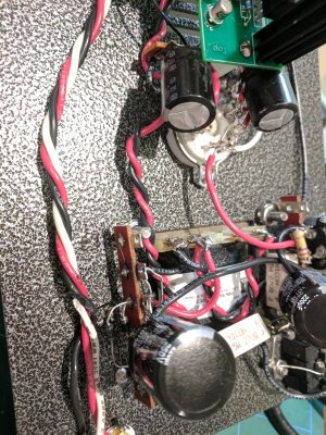
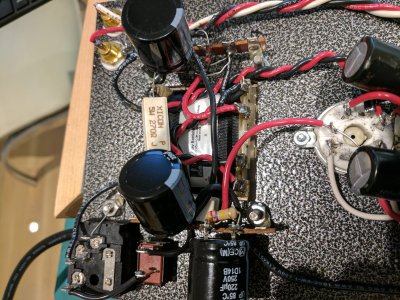
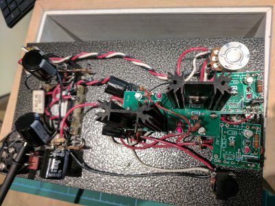
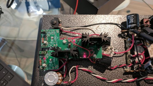
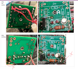
I attached a few pics, please let mewhich part is more helpful and I will take more pictures.

Really appreciate any help. I have some T1 and HD600 cans here that wait to be powered!

Many thanks for any hints!
 

Attachments

  • IMG_20170205_183409.jpg
    IMG_20170205_183409.jpg
    6 MB · Views: 52
  • IMG_20170205_181355.jpg
    IMG_20170205_181355.jpg
    5.2 MB · Views: 48
  • IMG_20170205_175857.jpg
    IMG_20170205_175857.jpg
    4.3 MB · Views: 57
Thanks,
Is there anyway to test or pinpoint the error without removing the speedball add-on? I do not have the resistors anymore.

btw: Only half of the LEDs are lighting upon the speedball boards, is this normal?

 
OK,
managed to get the wirebound resistors and removed the speedball addon.
It looks all good and it actually runs for the very first time.

Readings below
Terminal Resistance 

1  - *  - starting from 30
2 - *  - starting from 15  
3   - 0 ohms  - 0 
4   - *  - starting from 20 
5   - *  - starting from 50 
6   - 2.4K ohms  - 2.4 
7   - 2.9K ohms  - 2.9 
8   - 0 ohms  - 0 
9   - 2.9K ohms  - 2.9 
10   - 2.4K ohms  - 2.5 
12   - 0 ohms  - 0 
13   - * will climb slowly toward 270K ohms  - Slowly reaches 200 and then MM shows 1 
14   - 0 ohms  - 0 
20   - 0 ohms  - 0 
22   - 0 ohms  - 0 
B3   - 2.9K ohms  - 2.9 
B6   - 2.9K ohms  - 2.9 
RCA jacks: 
Ground lug   - 0 ohms  - 0 
Center pin   - 90K ohms—100K ohms  - Red: 85.9 white:102.3

Voltage
Terminal Voltage (VDC unless otherwise specified) 
1  -   75-90  -  86 
2   -  170  -  168 
3   -  0  -  0 
4   -  170  -  168 
5   -  75-90  -  85 
6   -  0  -  0 
7  -   100  -  108 
8   -  0  -  0 
9   -  100  -  107 
10  -   0  -  0 
11  -   0  -  0 
12   -  0  -  0 
13  -   170  -  167 
14  -   0  -  0 
15   -  185  -  185 
20   -  0  -  0 
21   -  206  -  209 
A1  -   90  -  85 
A2   -  0  -  0 
A4  -   0  -  1 
A5   -  0  -  0 
A6   -  90  -  86 
A7   -  0  -  0 
A9   -  0  -  0 
B1   -  90  -  84 
B2   -  170  -  167 
B3   -  100  -  110 
B4  -   90  -  85 
B5   -  170  -  168 
B6   -  100  -  108 
B7   -  0  -  0 
B8   -  0  -  0 

It seems that all values are now in the correct range I hope.
What would be the best way to troubleshoot the speedball add-on?

Thanks!

 
You should go back through the Speedball manual and carefully review how you've mounted the TIP50 transistors.

We have since updated the Speedball manual to include a lot of large, red text to highlight that the way one mounts a TIP50 transistor is extremely important, and not mounting it correctly can cause the exact issue you had.
 
Thanks,

so I have assembled the speedball again, went step by step, re-soldered all points but unfortunately I get the same voltage readings again. The resistance is also off. I have the slight feeling that something is wrong with the two smaller boards. None of the LEDs are glowing. Especially on one small board the G terminal next to the 150k ohm resistor seems to be broken as it was really tough to solder. The solder just doesn't want to stick there. Looks like I burnt the ring.

Any help how I can debug the error would be greatly appreciated.


1      *
2 *
3 0
4 *
5 1

6 2.5
7 *
8 0
9 *
10 2.5
12 0
13 *
14 0
20 0
22 0
B3 *
B6 *


1 68
2 66
3 0
4 64
5 52
6 0
7 55
8 0
9 46
10 0
11 0
12 0
13 61
14 0
15 116
20
21 172
A1 49
A2 0
A4 0
A5 ?
A6
A7
A9
B1 50
B2 60
B3 45
B4 47
B5 58.5
B6 42.6
B7 0
B8 0


There are no resistance checks in the Speedball manual you are working with.

Remove the 6080, leave the 12AU7 in, then recheck the voltages at terminals 1, 2, 4, and 5. 

-PB
 
Thanks Paul,
Unfortunately I didn't have time for the last 6months, but now I have a free week where I finally want to finish it!

I have removed the 6080 and left only the 12AU7 as suggested.

I set the multimeter to 600
1 - 208
2 - 198
4 - 198
5 - 193

The picture below shows which LEDs are glowing when both tubes are installed. Not sure if this helps.

Thanks
 

Attachments

  • IMG_20170916_125748.jpg
    IMG_20170916_125748.jpg
    926.7 KB · Views: 23
Would you unscrew the two small boards and flip them over, then post another pic?  Do the LED's on the 9 pin socket illuminate? (Please don't do anything to them or with them if they don't, it's more an indicator of a different problem)

You said the stock amp was working, did it pass all its voltage checks? 

Can you tell me a bit about the solder you're using?  There seems to be an unusual amount of flux on the boards.
 
A side comment. The wires from the RCA's and the vol pot are twisted here and they should be braided. I believe they are braided to minimise noise and cross talk. Does it make much difference?
 
Both LEDs on the 9pin luminate.
Voltage check passed on the stock amp. I still have the numbers
1 - 86
2 - 168
3 - 0
4 - 168
5 - 85
6 - 0
7 - 108
8 - 0
9 - 107
10 - 0
11 - 0
12 - 0
13 - 0
14 - 167
15 - 0
16 - 185


The solder says it is Multi-core solder (60% tin, 40% lead)
Also this is my first time soldering, plus I resoldered it a few times, which explains the massacre on the board.

The picture shows that I connected the black cable on G directly with the resistor on one board as the the ring on the board was destroyed by my soldering.
I marked it with X.  This is the board where the LED does glow however. Restistance seems to be OK as well.


Attachments

  • Crack boards.png
    Crack boards.png
    2.1 MB · Views: 31
If you have an adjustable soldering iron, turn it all the way up.  If you don't have an adjustable soldering iron, you need to leave it on your solder joints longer. 

The issue I'm seeing here is a lot of cold solder joints that look like they either haven't been heated enough or have way too much solder in them (or both).  My suspicion is that you need to reheat all of the solder joints on all your PCB's.
 
OK,
I resoldered all of the joints on all boards and spotted a mistake I made on the board where the LED wasn't working. the red wire wasn't attached to I but to O.
Now the LED is illuminating, btw. is it correct that just one LED per board should light up?
Both LEDs on the 9pin light up but are quite dimmed after a few seconds in.

Voltage readings, most of them 50% of what they should be
1-70-90->54
2-170->68
3-0->0
4-170->65
5-75-90->54
6-0->0
7-100->48
8-0>0
9-100->47
10-0->0
11-0>0
12-0->0
13-170->62
14-0->0
15-185->120
20-0->0
21-206->173

A1-90->51
A2-0->0
A4-0->0
A5-0->0
A6-90->50
A7-0->0
A9-0->0

B1-90->50
B2-170->60
B3-100->45
B4-90->50
B5-170->60
B6-100->45
B7-0->o
B8 -0->0

-


This is usually an issue with the solder joint on the center leg of the MJE-350 (assuming there are no other problems).  If the LED's on the 9 pin socket aren't lit up (permanently), this further suggests that current isn't passing through the small PC boards, and this is generally a mistake of either:

1.  Solder joints, especially on the MJE-350, as mentioned above.
2.  2N2222 transistors installed in place of the 2N2907.
3.  A missed or improper connection into the amp when installing the boards.
4.  A Crack that wasn't working prior to putting in the Speedball.
5.  Backwards MJE-350's (yours look OK).

-PB
 
Thanks, I'll go through the steps again.
When I removed the 6080, then both LED on the 9pin socket were lit up and also stayed until I switched it off again. But then the 2 LED on the bigger board were rather dimmed.
Not sure whether this matters.
 
alesi said:
Thanks, I'll go through the steps again.
When I removed the 6080, then both LED on the 9pin socket were lit up and also stayed until I switched it off again.
Please recheck your voltages at terminals 1, 2, 4, and 5 under these conditions.

alesi said:
But then the 2 LED on the bigger board were rather dimmed.
Not sure whether this matters.
This isn't super important right now.  The focus is on getting the 12AU7 and the small C4S boards loading it operating properly. 
 
I went through each solder joint again, not only on the boards. I get the same readings, 1,2,4,5 -> ~195
What should be the correct reading without 6080?

Coming weekend I plan to remove the speedball addon again, detach all components and start from scratch.
However I would like to replace some components, as I want be sure that it is not a broken part that is causing the issue.
Are there any components on the Speedball addon you think might be worth replacing. Just to be sure.

Thanks.
 
The voltages should be between 60 and 100V on terminals 1 and 2 with no 6080 present.  You have a separate issue on the large PC board feeding the 6080 that needs to be dealt with separately but can't be properly dealt with until the front half of the amp is working properly.

If you go to remove all the components on the PC board, you will likely destroy the board.  Can you post top and bottom photos of the PC boards as they are now?  By chance, would it be possible to get a DC voltage reading on A3 and/or A8?

-PB
 
Back
Top