Crack help [resolved]

Junksleep

New member
Hello to all, and tanks for looking.  Just finished wiring a Crack 1.1 and need a bit of guidence . Resistance test was good but voltage test has problems.  This is with 120 v line . Leds are alive. No RCA plug ins.
Terminal 1.    158v
                2.    199v
                3.    0
                4.    192v
                5.    90v
                6.      0
                7.    98v
                8.      0
                9.      0
                10.    0
 
I checked with ohm meter and continuity , good , but i'll reflow them tomorrow. Thinking about just stripping all caps and resistors and rebuilding.
 
I’d really suggest taking a more methodical,  conservative approach instead of tearing it down and starting from scratch. Post some photos, check out solder joints and reheat where necessary. There aren’t many scenarios where a clean slate is required.
 
Junksleep said:
Leds are alive. No RCA plug ins.
                1.    158v
                2.    199v
                4.    192v
                5.    90v
                7.    98v
This is a somewhat improbable set of voltages.  Seeing 2 be different than 4 is very odd, as they are connected by a piece of wire.  It would be extremely unusual for 5 and 7 to be OK with terminal 1 being at 158V, and also odd to have both LEDs lit on the 9 pin socket under these conditions. 

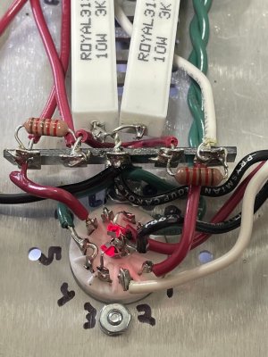
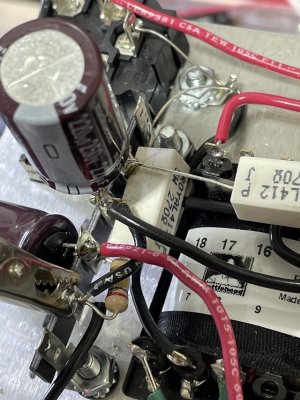
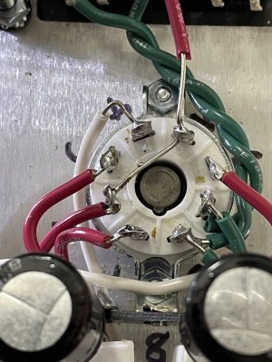
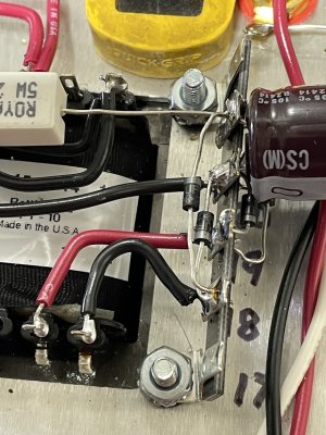
I'd recommend posting some build photos if possible.  Also have a good, long look at the solder joint on the headphone jack where the black wires connect.  Often when we run into voltages on this kit that don't make a ton of sense, one of those black wires won't be captured by solder and odd things will happen...
 
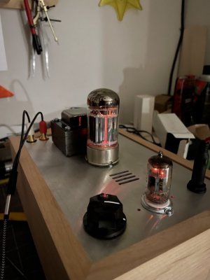
Some clarity may be had today.  The disparity volts on 2/4 Could have been my typing error making that little chart/table. This am I have swallowed any pride I had and reflowed all solder connections, after the reflow work the resistance checks are good/spot on. The voltage check is better but not right. Terminal 1+5 are 98.
Terminal 2+4 are 224.  7+9 are 0 volts, and the power tube is arcing blue . B3 + B6 are also 0 volt. Hoping  a tube will make right the voltage readings.  Thanks for looking.

Junk
 

Attachments

  • IMG_1581.jpg
    IMG_1581.jpg
    221.9 KB · Views: 7
  • IMG_1584.jpg
    IMG_1584.jpg
    237.8 KB · Views: 5
  • IMG_1582.jpg
    IMG_1582.jpg
    226.1 KB · Views: 4
  • IMG_1583.jpg
    IMG_1583.jpg
    247.7 KB · Views: 5
Having another look at your voltages, the 0V at 9 isn't great.  Are you able to measure the resistance at terminal 9?  0V there indicates either half the 6080 isn't working, or there's some kind of issue preventing voltage from developing across the 3K resistor.  The 6080 arcing would tend to indicate that there may be a short there causing excessive current draw, but the 224V at pins 2 and 4 tells me that half of the 6080 isn't drawing any current at all.

If you are able to verify 3K resistance at terminal 9, I'd try a different 6080.
 
Thanks Paul,  I was hoping it was the tube, thats easy. Got two coming already. I did confirm late last night 3k ohms at pin 9.

Junk
 
New power tube installed , amp is happy now . All volts and ohms are correct, thanks to all.
 

Attachments

  • IMG_1596.jpg
    IMG_1596.jpg
    122.4 KB · Views: 7
Back
Top