stevenbravo1410
New member
Hey guys! Im building the Speedball update, i already assembled the Crack and it worked perfectly, so after enjoying it a few hours i decided to install the Speedball upgrade
Everything regarding voltage and checks work perfectly until i check the OB in the small board which reads double what it should at 150V
I followed the diagram and check the R1 resistances in the small board and both mark 238 Ohms, so i checked if the orientation was right and yeah it was, and yes the lower tube fully lights each section
One thing i noted tho is that one of the LEDs in the 9pin socket stopped turning on, the one connected to A8 is working fine, but the other one doesnt turns on
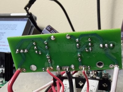
Here i send some pictures to have as reference.
I already tried soledring the MJ correctly, reflowed it 3 times as well as the whole board and it just simply lowered the OB voltage by 12v give or take, another note, im using some black and white cables from the crack kit to connect the pcb because the wire that came with the speedball broke several times while handling and moving the pcb board, i have the correct wire cutter, did it manually to try as well, so i got tired of those cables breaking and i used some of the crack, but the problem already existed with the previous cables and the new ones helped lower the voltage a little bit.
One thing i do notice when i turn on the kit is that the left LEDs of the pcb board turn on first, and then after a delay of around 2 or 3 seconds the LED/ of the right then turn on, i dont know if the info helps but its what i observed
Thanks in advance for the help!


Everything regarding voltage and checks work perfectly until i check the OB in the small board which reads double what it should at 150V
I followed the diagram and check the R1 resistances in the small board and both mark 238 Ohms, so i checked if the orientation was right and yeah it was, and yes the lower tube fully lights each section
One thing i noted tho is that one of the LEDs in the 9pin socket stopped turning on, the one connected to A8 is working fine, but the other one doesnt turns on
Here i send some pictures to have as reference.
I already tried soledring the MJ correctly, reflowed it 3 times as well as the whole board and it just simply lowered the OB voltage by 12v give or take, another note, im using some black and white cables from the crack kit to connect the pcb because the wire that came with the speedball broke several times while handling and moving the pcb board, i have the correct wire cutter, did it manually to try as well, so i got tired of those cables breaking and i used some of the crack, but the problem already existed with the previous cables and the new ones helped lower the voltage a little bit.
One thing i do notice when i turn on the kit is that the left LEDs of the pcb board turn on first, and then after a delay of around 2 or 3 seconds the LED/ of the right then turn on, i dont know if the info helps but its what i observed
Thanks in advance for the help!
")

