Hi all. Appreciate the help in advance. I finished putting together the Crack 1.1 OTL Headphone Amp Kit. I'm having two issues that I'd like help with.
One, the LED attached to A9 does not light up. The other LED does light up.
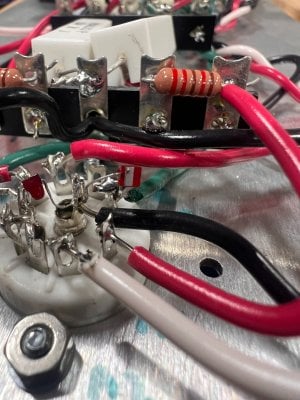
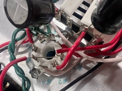
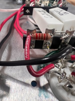
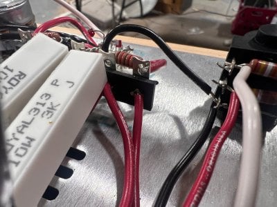
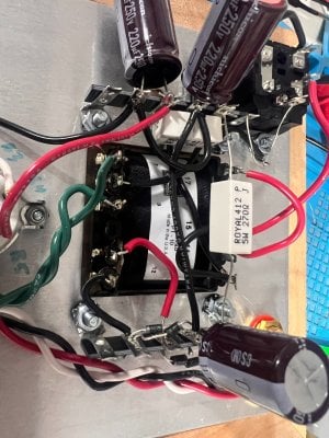
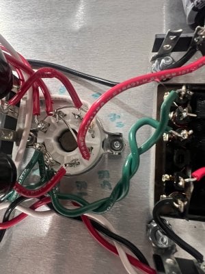
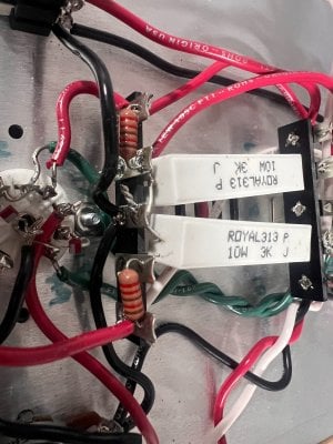
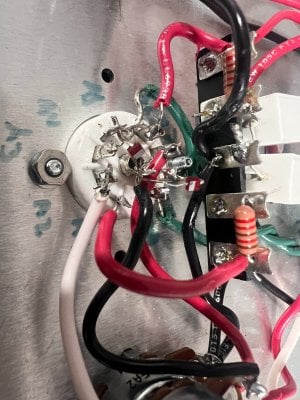
The second issue some of the voltages are significantly higher than what the documentation states. I've attached some photos of the build, and the resistance tests all passed. Here are the voltages:
Any pointers to where I should look would be appreciated. I traced back through the circuit and I *think* I have everything connected correctly. Thank you!
One, the LED attached to A9 does not light up. The other LED does light up.
The second issue some of the voltages are significantly higher than what the documentation states. I've attached some photos of the build, and the resistance tests all passed. Here are the voltages:
| Contact | Measured Voltage | Expected Voltage | High/Low/Normal |
|---|---|---|---|
| 1 | 154 | 50-100 | High |
| 2 | 168 | 170 | Normal |
| 3 | 1.1 | 0 | Normal |
| 4 | 169 | 170 | Normal |
| 5 | 76 | 50-100 | Normal |
| 6 | 1 | 0 | Normal |
| 7 | 153 | 90-115 | High |
| 8 | 1 | 0 | Normal |
| 9 | 104 | 90-115 | Normal |
| 10 | 1 | 0 | Normal |
Any pointers to where I should look would be appreciated. I traced back through the circuit and I *think* I have everything connected correctly. Thank you!