Hi there,
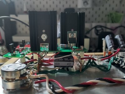
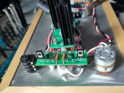
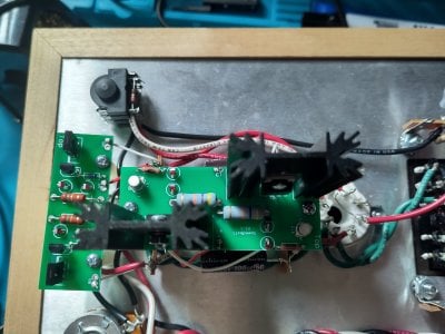
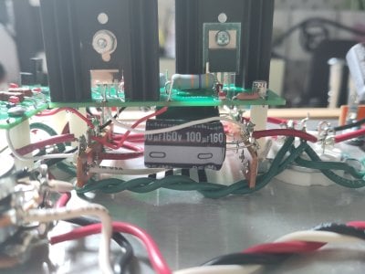
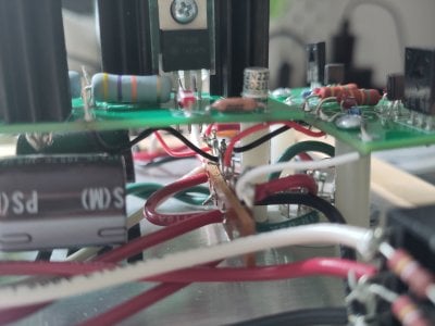
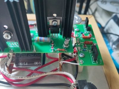
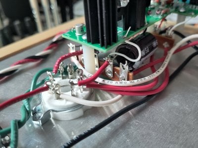
after installing the Speedball upgrades on my Crack step by step. I first installed the first upgrade board with successful checks and tested it for a few days. Sound was great. After that, I went for the second board. Resistance and voltage checks were within the given tolerances. It worked for about five minutes, sound was muffled, which was strange changed gear for troubleshooting, but the resistor R1A blew up.
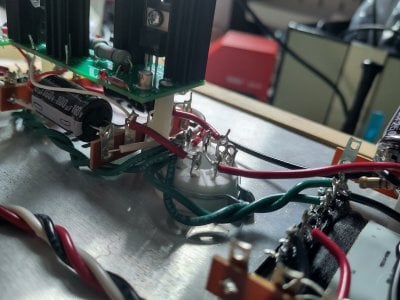
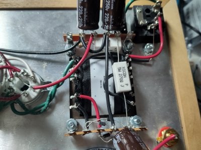
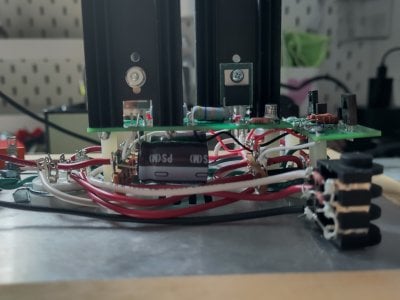
I'm a bit lost what the root cause could be. Wiring looked fine and the MOSFETs are properly isolated. The Crack itself ran fine for a few years. I've attached images of the build.
after installing the Speedball upgrades on my Crack step by step. I first installed the first upgrade board with successful checks and tested it for a few days. Sound was great. After that, I went for the second board. Resistance and voltage checks were within the given tolerances. It worked for about five minutes, sound was muffled, which was strange changed gear for troubleshooting, but the resistor R1A blew up.
I'm a bit lost what the root cause could be. Wiring looked fine and the MOSFETs are properly isolated. The Crack itself ran fine for a few years. I've attached images of the build.
Attachments
-
 IMG_20250919_123041.jpg1.4 MB · Views: 13
 -
 IMG_20250919_123052.jpg1.6 MB · Views: 13
 -
 IMG_20250919_123057.jpg1.4 MB · Views: 13
 -
 IMG_20250919_123105.jpg1.1 MB · Views: 11
 -
 IMG_20250919_123111.jpg1.5 MB · Views: 11
 -
 IMG_20250919_123116.jpg1.4 MB · Views: 10
 -
 IMG_20250919_123149.jpg1.1 MB · Views: 12
 -
 IMG_20250919_123158.jpg997.2 KB · Views: 14
 -
 IMG_20250919_123208.jpg898.1 KB · Views: 13
 -
 IMG_20250919_123213.jpg1.5 MB · Views: 14