BeePre Build Help Needed [resolved]

Thank you Paul and grufti.

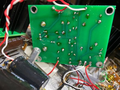
The joint missing solder on the back of the B side filament board was actually soldered from the top, but I soldered it from below just now as well.
Thank you for spotting that.
The B-side LEDs are all still out, all four of them now, and the voltage at termnial 12 is 0.04V.
The A-side LEDs all come on, but then go out at the same time after ten minutes of power on.

The solderer is a 63 year-old man with vision impaired by a central retinal vessel occlusion in the left eye, not too proud to use magnification and loupes and direct overhead light.
Iron is a Hakko 936 usually set at 850F on the Hakko dial.
Soldering tip is a 1.5 mm "D" wedge, Hakko brand.
Tip cleaning with Hakko brass wool and a wet sponge.
Solder is Cardas quad eutectic flux core.
Copper wick method used to remove solder when necessary.
Knipex cutter used for wire cutting, stripping.

Appreciate your help,
Mark
 
Solder joints that look good from above but show no solder from below are solder joints that aren't heated enough.  The solder needs to be heated enough to flow through the board, if it's not the flux can actually act as an insulator and prevent the joint from working properly.  It might also help to turn that station up as hot as it will go.
 
So, I melted the power switch going over all the joints again trying to make sure to get them appropriately hot for good contact. This was very easy to do! I've ordered another power switch and will post voltages again when the new switch is installed, but a quick connect still shows the four LEDs on the B side are dark.
Mark
 
New switch installed.
No LEDs on B side.
Voltages freshly measured.
Numerous off voltages on B side.

1-  4.86V
2-  91.7V
3-  0
4-  9.86V
5-  0
6-  145.3V
7-  0
8-  0
9-  0
10-  189V

**11-  187V
12-  0
13-  0
14-  0
**15-  192V
16-  4.91V
17-  16.0V
18-  0
19-  9.89V

20-  0
21-  0
22-  214V
23-  0
24-  0
25-  217V
26-  0
27-  0
28-  0
29-  7.02V

30-  7.02V
31-  14.1V
32-  0
33-  0
34-  14.1V
35-  7.01V
36-  7.02V
37-  0
38-  0
39-  0
40-  216V
41-  0
42-  0
43-  217V
44-  0
45-  0
46-  216V
47-
48-  0
49-  0
50-
51-  0

A1-
A2-  91.5V
A3-  0
A4-

B1-
**B2-  16.0V
B3-  0
B4-

C2,D2-  0,0
**C3,D3-  3.85,1.95V
**C7,D7-  145,184V
**C9,D9-  145,182V


Mark
 

Attachments

  • B1.jpg
    B1.jpg
    644.1 KB · Views: 10
  • B2.jpg
    B2.jpg
    771.7 KB · Views: 10
  • B3.jpg
    B3.jpg
    616.4 KB · Views: 10
  • B4.jpg
    B4.jpg
    660.6 KB · Views: 15
I would swap the high current C4S boards from side to side. 

Just let me know if the problematic voltage at OB and pin 2 on the 4 pin socket stays or moves. 
 
Thank you Paul.

C4S boards swapped.

B2 now 90.5V
OB side B now 90.6V
A2 now 4.8V
OB side A  now 16.7V
LEDs lit on side B.

The voltage problem does follow the C4S board.

Mark
 
The easy way to resolve this would be to just order a replacement board, heatsinks, transistors, and resistors from replacementparts(at)bottlehead(dot)com.

Otherwise problems like this are 90% soldering, 8% improper build, and 2% other.  You can set your meter to beep for continuity to check each pair of transistor leads to look for shorts, but that seems unlikely.  You can also use the diode check function to check the LEDs.  Sometimes if you have LEDs that sit around for a long time before being soldered, they can absorb moisture and fail when they are soldered and that moisture is quickly cooked out.
 
Dear Paul, grufti, and Bottleheaders,
Rebuilding the C4S board resolved the issues and the BeePre is now operating in my main stereo. It sounds quite good and is an improvement over the Foreplay, although it is slightly but noticeably microphonic. I'm working on some isolation and damping now.
Thank you for your help!
Mark
 
Back
Top