4-pin socket placement, large and small holes [resolved]

lesouthern

New member
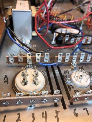
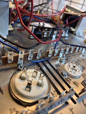
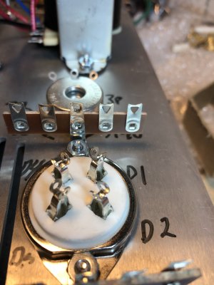
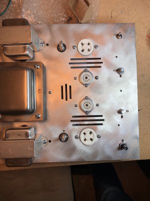
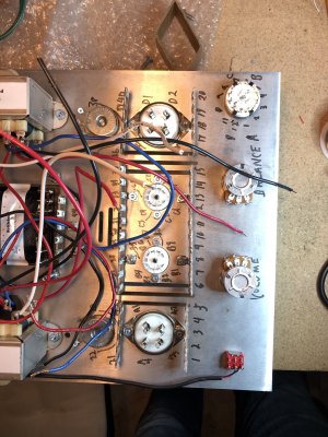
Hi I'm having difficulty from the instructions (page 14) seeing the difference between the larger and smaller holes on the 4-pin tube sockets.
"The larger holes MUST face the back of the chassis"

Are these installed correctly? Any other indications I can see they are?

thanks,

Larry
 

Attachments

  • IMG_6470.JPG
    IMG_6470.JPG
    2.5 MB · Views: 9
  • IMG_6471.JPG
    IMG_6471.JPG
    2.3 MB · Views: 1
  • IMG_6472.JPG
    IMG_6472.JPG
    1.9 MB · Views: 1
  • IMG_6473-0.JPG
    IMG_6473-0.JPG
    2.3 MB · Views: 2
This is more easily seen from the top, could you post a couple of photos of the tops of the sockets with the hum pot shafts included for reference?

Thank you for stopping your build and coming here to seek help, it's a lot easier to get this ironed out now rather than after the amp is soldered up!
 
Another way of checking: turn the chassis right-side up in the base and insert the 2A3 tubes - the right way will be snug, but doable; the wrong way won't work unless you use way too much force to insert the pins. Once you figure out the right way, check whether the fat pair of pins are farthest from the front, and the skinnier pins closest to the front. If they are, the sockets are oriented correctly. If not, they need to be rotated 180 deg.

cheers, Derek
 
thank you, here are pictures of my current installation from top views, is this right?
 

Attachments

  • B2C9ED72-D0D9-4FD9-B2D2-8AA1893F8AC2.jpg
    B2C9ED72-D0D9-4FD9-B2D2-8AA1893F8AC2.jpg
    1.5 MB · Views: 34
  • EE757F31-D5DC-4337-95CC-9D1B84C91827.jpg
    EE757F31-D5DC-4337-95CC-9D1B84C91827.jpg
    1.5 MB · Views: 15
One is correct, one is backwards.  The ceramic wafer has enlarged holes for the larger pins, which aren't so hard to see from the top.
 
Yes I see exactly what you are talking about now. Glad I could fix it at this phase.

Back to practicing soldering.

thanks for the help
 
Back
Top