illusineer
New member
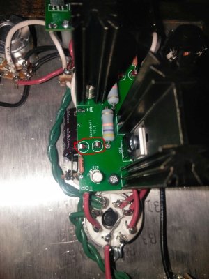
OA - 110V
OB - 102V
G - 13V
B+ - 206V
One of my voltages ain't right :-\ it also reads 13v on the small board test for B-A/B. I plugged in my headphones and only got sound from the right. My amp was working fine before I put the pcbs on it. Also when I was soldering wires on the terminals for the big board sparks popped near the capacitors while I was affixing the wire ends with my pliers (this was after cutting out the 10k 3ws and before putting the big board on). The amp was unplugged but didn't blow the fuse, idk if that has anything to with it or I shorted out the capacitors somewhere while they still had charge.