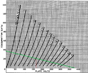
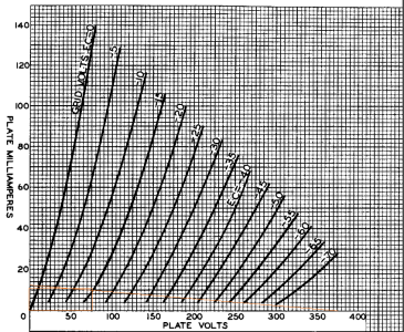
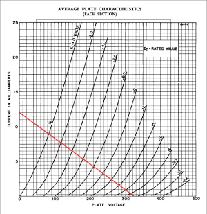
Wright Mono 8 Schematic

Caucasian Blackplate said:
That's also not particularly plausible.  (Run it through spice or draw a 270 Ohm load line on the datasheet)

I would say that there's a white or silver band between red and violet that just isn't super visible. That would give an operating point of about 20V of bias and 20mA into a ~3K load assuming there's about 400V of B+ available.  It still seems a little off, but it will pass signal (the lower values of plate load will choke the available signal voltage at the grid of the 300B).

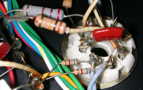
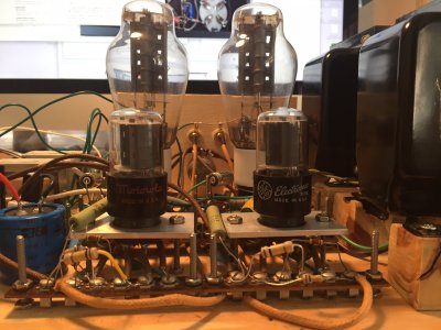
So, I read what you said and thought about it for awhile, and earlier this evening received pics from inside the other amp. The rake lighting in the attached image shows that there is no other stripe on that resistor -- it really is 270 ohm (unless the brown multiplier stripe is a discolored red or orange, but I don't think so).

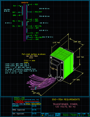
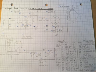
I also learned that the power transformer was manufactured by DeYoung and is labeled with the number DMI 500-7694 0050, which Google shows me was also used on the WPA 3.5. I've written to DeYoung to ask for the specs, but it's possible that the Mono 8 ran at or near 2A3 voltages. Maybe he had one PT made for multiple models, and there was a higher voltage tap available for the Mono 8, but we'll see.

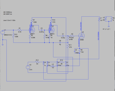
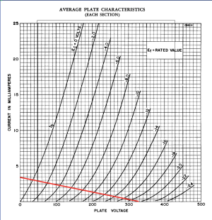
I tried the 250Vak and 300Vak 300B operating points in LTSpice just to see what the 6DN7 looked like.

250V (63mA)
B+ -- 306V
Plate/Cathode 1 -- 117V/4.4V (1.4mA)
Plate/Cathode 2 -- 257V/13.5V (13.5mA)

300Vak (77mA)
B+ -- 367V
6DN7 Plate/Cathode 1 -- 140V/5.3V (1.7mA)
6DN7 Plate/Cathode 2 -- 309V/16.3V (16.3mA)

In either case it can take about a 2V signal before clipping, so, feasible for use with a line preamp.
 

Attachments

  • 6DN7-closeup-v2.png
    6DN7-closeup-v2.png
    2.3 MB · Views: 17
jdrouin said:
6DN7 Plate/Cathode 2 -- 309V/16.3V (16.3mA)
16.3mA across a 270 Ohm resistor is 4.32V of drop.  That stage of the driver can swing down nice and far, but can only swing up a few volts...

(You'll also generate a lot of distortion with this loading)

 
Correction: The amp was not the later 6DN7 version but the earlier 6EM7 version. Silk screening on the chassis says 5Y3 Russian, 6EM7, and 300B, and the owner happens to be using a 6DN7.

I also corrected some schematic errors, making sure all of the back-bias components connect to their spots in the PS and that the negative side of the DC voltage source connects to the PS ground bus, where the PT center tap connects on the real thing. Also the ground bus connects to the ground tab on the RCA input jack, I suppose to carry the ground path through the interconnect to the line preamplifier. I'll have to redraw it but I think this is technically more accurate.

So, inserting a 6EM7 into the model and keeping the 300B at 300Vak, we get the following:

B+ 353.3V
300B -- 300Vak/59.2mA
6EM7-1 plate/cathode -- 171.6V/2.4V (776uA)
6EM7-2 plate/cathode -- 240V/33.9V (33.9mA)

That's pretty low current on that first stage of the 6EM7.

The model will take an almost 4V input signal before clipping.
 

Attachments

  • mono-8-6em7-beta-01.png
    mono-8-6em7-beta-01.png
    104.8 KB · Views: 20
The unbypassed cathode resistor of 1000 ohms provides considerable negative feedback. In conjunction with a 270 ohm plate load, the gain of that river stage is around 0.2 (i.e. -14dB. It also increases the effective plate resistance of the driver triode - that at least is not an issue since the output impedance is swamped by the 270 ohm resistor.

The loss of gain means also a loss of peak voltage. If the 6EM7 driver stage is running 33.9mA quiescent, then cutting that current to zero will produce the peak positive excursion of 9.15 volts - nowhere near the 45v needed to drive the output tube grid. PB already made that point, I'm just amplifying it (sic).

For the above reasons, I still don't believe it is a 270 ohm resistor, at least in the original design.

 
"For the above reasons, I still don't believe it is a 270 ohm resistor, at least in the original design."

I think I understand your reasons, as I'm still learning basic tube operation. However, as an aside, it's funny that every time I post a George Wright schematic, people find some utterly baffling choices that can take up a lot of screen real estate. The 522K resistor from 6SN7 pin 6 to 2 in the WPA 3.5 is another case in point, where your own foray into the topic sheds some light on its role: https://www.audioasylum.com/messages/set/72516/re-wright-3-5s.

As a novice, it's amusing to see how George marched to his own drumbeat and continues to puzzle even experienced hands from the beyond. Wish I'd gotten into this earlier, as it sounds like he was a great guy and I would've loved to meet him.

Back to the amp, it appears to me that the 270ohm resistor is indeed intentional despite the loss of gain. The owner of the amps says he bought them directly from George in 2001 and they've never been modified. Maybe the oral history is inaccurate due to faulty memory or something, but every day he listens to and enjoys the very amps we're picking apart here. So it's not just a hypothetical.

Let's suppose that what I see as a brown multiplier stripe in several images is a discolored red or orange one. CB has already given his doubts about that, but here's how the model changes assuming a red (x100) or orange (x1000) stripe with the same op point of 300Vak/60mA on the 300B:

Red stripe -- Rp2 2.7K
B+: 354.4V
300B: 300Vak (60.2mA)
6EM71 plate/cathode: 186.4V/2.6V (834.4uA)
6EM72 plate/cathode: 196V/27.4V (27.4mA)
Can take up to 3.25V singal before clipping

Orange stripe -- Rp2 27K
B+: 357.8V
300B: 301.3Vak (63.3mA)
6EM71 plate/cathode: 227V/3.1V (994uA)
6EM72 plate/cathode: 70.9V/9.5V (9.46mA)
Can take up to 0.7V signal before clipping

And one final thing I want to bring up because it could be a clue to the op point of 6EM7 section 1: the 3.09K carbon film resistor at Rk has the number "2" printed on it in both amps. I've never seen that before. Does it have a bearing on the resistance value? Pic attached.


Attachments

  • 6EM7-closeup-amp-a.png
    6EM7-closeup-amp-a.png
    707.2 KB · Views: 19
  • 6EM7-closeup-amp-b.png
    6EM7-closeup-amp-b.png
    723.2 KB · Views: 16
jdrouin said:
Red stripe -- Rp2 2.7K
B+: 354.4V
300B: 300Vak (60.2mA)
6EM71 plate/cathode: 186.4V/2.6V (834.4uA)
6EM72 plate/cathode: 196V/27.4V (27.4mA)
That is making a lot more sense.  In this case, 73-ish volts are dropped across the 2.7K resistor, so there's adequate compliance between the plate and power supply to get some decent signal voltage out of that stage.

On the possibility of 27K, now the plate voltage is so low that you're running out of room in the opposite way compared to the 270.
 
Caucasian Blackplate said:
That is making a lot more sense.  In this case, 73-ish volts are dropped across the 2.7K resistor, so there's adequate compliance between the plate and power supply to get some decent signal voltage out of that stage.

That's what I thought too. What about the less-than-1mA current on the first stage though? Is that too low? I've never modeled anything which had that little current before.
 
The 6EM7 small triode (first stage) has a high gain (60) and a high plate resistance (40kOhm), but a lowish transconductance (1600uMho). That means it will necessarily run at a low current.

A fairly common "standard operating point" is to use a beam resistance (plate-cathode voltage divided by plate current) of 5 times the plate resistance. That is almost exactly what you have.

The other issue is whether the first stage can drive the second stage Miller capacitance, which is at most 50pF, probably closer to 30pF with the unbypassed cathode resistor. The calculation is a bit tedious, but you want the plate quiescent current to be 5 times the peak current needed to drive that capacitance at 20kHz. To do the calculation, you need to know the signal voltage peak at the second stage grid, which depends on the gain of the second stage. The unbypassed cathode resistor makes that voltage. That takes more than just the data on the spec sheet, so I'll leave it as an exercise for the reader  :^)
 
Thanks for walking me through that, Paul. I'll look in Morgan Jones for the calculations needed to figure out the peak and quiescent current needed to drive a given Miller capacitance at 20kHz.

The owner of the amps was kind enough to measure the 6EM7 second plate resistor, and it's 25.7K -- so that's an orange stripe, making it a 27K 5% resistor.

That means that with the rest of the circuit as it is in situ, using a 300Vak/63mA op point on the 300B, the model is as posted above, or:

Orange stripe -- Rp2 27K
B+: 357.8V
300B: 301.3Vak (63.3mA)
6EM71 plate/cathode: 227V/3.1V (994uA)
6EM72 plate/cathode: 70.9V/9.5V (9.46mA)
Can take up to 0.7V signal before clipping
 
I just heard back from an engineer at DeYoung, who gave me the specs and a drawing of the DMI 500-7694 they used to make for George. The HV winding is 620VCT 100mA. At 310V per side, it confirms my suspicion that the Mono 8 ran at closer to 2A3 voltages.

The drawing also clears up a mystery encountered in the 6EM7 version of the amp, where a light blue and a white/yellow wire from the PT are soldered together on a tab near the PS but are not connected to anything else. Turns out they are legs of the two 2.5V windings, which combines them into a 5V winding for the 300B filament.

It's hard to read, but the two yellow wires are a 5V 2A winding for the rectifier.

Just thought I'd share here.
 

Attachments

  • DMI-PT.png
    DMI-PT.png
    60.2 KB · Views: 21
jdrouin said:
The owner of the amps was kind enough to measure the 6EM7 second plate resistor, and it's 25.7K -- so that's an orange stripe, making it a 27K 5% resistor.
Orange stripe -- Rp2 27K
B+: 357.8V
6EM72 plate/cathode: 70.9V/9.5V (9.46mA)
Oh thank goodness, that makes a bit more sense.  You won't find a lot of sympathy on this forum for running a triode at 7% of its maximum dissipation.  With 375V available,  a 10K load line looks pretty nice.  25mA/20V of bias puts you on a reasonably linear cross section of the curves with gobs of headroom (but be sure your power transformer can deliver the extra current).
 

Attachments

  • 6EM2 10K 375V.png
    6EM2 10K 375V.png
    218.7 KB · Views: 10
  • 6EM7 27K 375V.png
    6EM7 27K 375V.png
    223 KB · Views: 9
Thanks for that, CB.

I just came across a thread at AA where an owner of a Mono 8 w/6EM7 reports that George said a 6SN7 (among other tubes) could be swapped in place of the 6EM7, but for less gain.

https://www.audioasylum.com/cgi/t.mpl?f=set&m=1475

It makes me wonder if perhaps George did not substantially change the circuit for the Mono 8 for each "new" driver tube over the years, but kept it more-or-less the same and simply offered it with different input/driver tubes. Do any of you who knew George know anything about that?

Looking back over the images of a Mono 8 w/6SN7 that I posted at the beginning of the thread, with the new knowledge gained in the meantime, it appears the plate and cathode resistors are largely the same as in the 6EM7 model (with maybe a few ohms difference on triode 1 Rk) and that triode2 uses a bypass cap (the little white one that's hard to see) that's not in the 6EM7 model.

Back in reply #2, CB suggested a 470uF/10V bypass cap at 6SN7 Rk2. The little white one in the pic says "120" but I can't tell what that pertains to. It looks like a metalized film type rather than an aluminum electrolytic.

Anyway, putting a 6SN7 into the LTSpice model, with Rp1 100K & Rk1 3K | Rp2 27K & Rk2 of 1K, and 323V B+ available to that tube (there's 357V B+ for the 300B), we get:

B+ -- 323V
6SN71 plate/cathode -- 139V/5.5V (1.8mA)
6SN72 plate/cathode -- 177V/5.4V (5.4mA)
Can take up to 0.7V input signal before clipping

I tried my hand at load lines (attached), which look OK though I'm not sure I did it right.

6SN7 Triode 1:
B+ 323V
Rp 100K
323/100K = 3.23mA

So the line goes from 3.23 mA at 0V to 0mA at 323V. The line seems to match what I get in the model as 1.8mA at 139V. Does that seem correct?

6SN7 Triode 2:
B+ 323V
Rp 27K
323\27K = .0119

Let's round that to 12mA at 0 volts and 0mA at 323V. Likewise, this line seems to match the 177V/5.4mA point on the model.

What do we think about that? Should I get the couple of resistors and caps that I'd need, and do it up on the breadboard tomorrow?


Attachments

  • 6SN7-triode1-load-lines.png
    6SN7-triode1-load-lines.png
    176.1 KB · Views: 10
  • 6SN7-triode2-load-lines.png
    6SN7-triode2-load-lines.png
    181.7 KB · Views: 9
George occasionally had people doing assembly for him. I'm afraid I don't know who. But perhaps someone who does know could point you to them, to see if they have any info for you.
 
Yeah, those load lines look to be drawn properly.

The 6EM7 triode 1 is super wimpy, and putting a 6SN7 in its place will run the 6SN7 sub-optimally.
 
Caucasian Blackplate said:
We also have that 1uF cap that's coupling some power supply noise to the output stage likely to cancel out some of the ripple in the high voltage supply. Your mystery cap could form an AC voltage divider with the 75K resistor to inject some more power supply noise onto the grid of the 300B.

For what it's worth, if you're building from scratch, I would leave out the 1uF cap, the 75K resistor, and the mystery cap with the 75K resistor.

I have all the parts for this build now except for that 1uF non-polarized metalized film in the PS that CB suggests removing. Maybe that's an RC snubber circuit meant to limit extreme voltage peaks from entering the power supply on startup, and protect components downstream?

While searching Mouser I came across an affordable Cornell-Dubillier snubber cap that would seem to fit the function there:

http://www.mouser.com/ProductDetail/Cornell-Dubilier-CDE/940C6W1K-F/?qs=sGAEpiMZZMv1cc3ydrPrF5lJsZdC82VlV9%252bBDCfCjzI%3d

The 4uF 10V silvery-blue cap that connects between the 270K and 75K resistors could also serve a similar function, I suppose, though that's in the ground network.

Attached is the (I hope) penultimate draft of the schematic and parts list for the Mono 8 w/6EM7. I missed the little coupling cap inside the 6EM7 and had to add it later as C0. Pending suggestions, I will do a nicer drawing and scan it better, and/or offer LTSpice files.

I only have one 6EM7 on hand and don't want to buy a matched pair, so I'm going to breadboard the 6SN7s to hear what we get and can tweak from there.

Need to get my hands on a pair of MQ TFA-204 right quick, though. The big 5K:8ohm Electra-Prints I'm using don't have a place in the lower voltage rows of the WE op points table.


Attachments

  • mono-8-6EM7-schematic-beta-01.JPG
    mono-8-6EM7-schematic-beta-01.JPG
    1.9 MB · Views: 23
The circuit is up and running om the breadboard, and sounding good on the test speakers. Right channel 6SN7 plates are a few volts higher than their left channel counterparts, but everything else is closer.

300Bs are now running at 310Vak/65mA, so a slightly larger dropping resistor after the rectifier tube, up from the 33ohm one currently in place, should bring it down to the target 300Vak/60mA.

Left
Rout -- 372
B+1 -- 370
B+2 -- 344
6SN7
P1 -- 148
K1 -- 6
P2 -- 186
K2 -- 5.8
300B
P -- 359
K -- 49
G -- -13 (DC)

Right
Rout -- 372
B+1 -- 370
B+2 -- 344
6SN7
P1 -- 153
K1 -- 5.8
P2 -- 193
K2 -- 5.7
300B
P -- 359
K -- 49
G -- -13 (DC)
 

Attachments

  • IMG_9538.JPG
    IMG_9538.JPG
    605.4 KB · Views: 53
Back
Top