Wiring replacement pot (Alps)

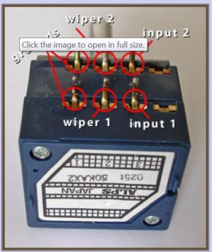
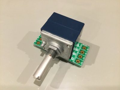
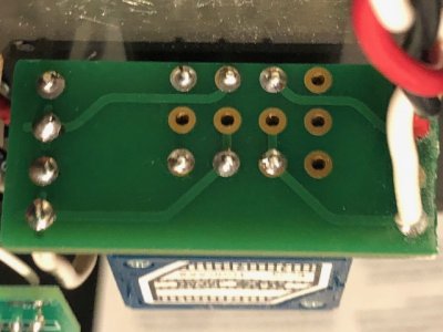
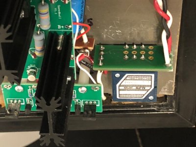
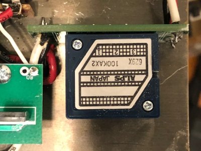
Breakout board arrived. There are three rows of four pins roughly in the (horizontal) center of the board. Three pins from the ALPS go into three of the four holes in the top and bottom of the three rows.  Kinda like this, using an X where an ALPS pin goes and an O where no pin goes:

XXXO
OOOO
XXXO


With this in mind, how do you experts recommend I wire this, and do you think I should get some little terminal blocks for the edges, or just solder directly to the board?

Thanks for any help!
 
This link/picture helped me on a past non-BH project.
(I soldered to the pins on that one!)
I was hoping to follow the traces on the board, once I get, it and figure it out.

http://www.diyaudio.com/forums/class-d/280137-wiring-alps-rk27-50k-potentiometer.html
 

Attachments

  • alps pot terminals.JPG
    alps pot terminals.JPG
    50.1 KB · Views: 100
If you got the break-out board PB linked, then there is only one way it can be mounted (as shown in the listing). Screenprint upwards & the RK27 centered.
Terminal blocks are ok in power supplies, but my preference is not to use them in the signal path.
 

Attachments

  • IMG_0140.JPG
    IMG_0140.JPG
    1 MB · Views: 86
There's a labeled "IN" side and an labeled "OUT" side.

The IN" side receives the signal from the RCA jacks. L is the white wire.  R is the red wire.  G is the black wire.  All holes labeled G on that board are connected together, so you don't (and shouldn't) add jumpers if one isn't used.

On the "OUT" side, R is the red wire going to the 9 pin socket, L is the white wire going to the 9 pin socket, and the black wires hook up to the soldered pads labeled G.
 
I'll just add that the picture shows that all of the ground connections have a dashed circle around the holes.  I assume that the ground connections in the center 4-hole portion of the board are for jumpers?  Or in other words the alps pins do not go into those holes?
 
diynewbie said:
I'll just add that the picture shows that all of the ground connections have a dashed circle around the holes.
Yes, the board uses a small ground plane for all the ground connections.
diynewbie said:
I assume that the ground connections in the center 4-hole portion of the board are for jumpers?  Or in other words the alps pins do not go into those holes?
What jumpers?  Which holes?

It looks like the board might fit a few different pots.  I wouldn't solder any wires to any of the holes other than the ones on the edge of the board where the terminal blocks go.
 
Caucasian Blackplate said:
Which holes?

BP, the link you provided for a breakout board shows 3 rows of 4 holes in the center of the board (not the IN or OUT outer holes).  The first/left holes in those 3 rows all indicate they are for ground.  So my question is are those hole meant to be used for jumpers or for the ground pins of the pot?  Sorry for the confusion.
 
diynewbie said:
  So my question is are those hole meant to be used for jumpers or for the ground pins of the pot?  Sorry for the confusion.
Since they are all connected together through the ground plane of the board, you do not need to add jumpers.  They are the ground pins of the pot.
 
A very fundamental question for you experts: Why do so many, including Doc B, believe that upgrading the volume pot is one of the first and best upgrades for the Crack (other than speedball)? (I'm not saying I disagree...I don't know enough to have an opinion. It's a sincere question with no subtext!) Can you tell me just what the benefit is of an upgraded pot? (And I'm in Colorado, so please no upgraded pot jokes.)
 
Cool beans regarding the circuit board.  I used 22 gauge from the RCA inputs to the Alps when I built my Crack several years back.  It was easier to wrap the pins with the smaller wire and it's been fine.  But, I went ahead and ordered a board anyway.  I'll end up doing the "upgrade" after I get the board and get bored.  I knew that these boards existed and meant to get one but forgot about them.  I was even thinking of drilling and etching my own at one point (I can make simple boards).    But thanks for the reminder. 
 
Rossputin said:
A very fundamental question for you experts: Why do so many, including Doc B, believe that upgrading the volume pot is one of the first and best upgrades for the Crack (other than speedball)? (I'm not saying I disagree...I don't know enough to have an opinion. It's a sincere question with no subtext!) Can you tell me just what the benefit is of an upgraded pot? (And I'm in Colorado, so please no upgraded pot jokes.)

Well, I'm far from an expert but the alps pot is noticeably smoother and less "scratchy" feeling than the stock pot.  Also seems well-sealed so I suppose it will be less likely to get dusty over time and require deoxit treatment etc.  It feels high quality like vintage audio equipment with a smooth, hydraulic feel when you turn it.  Personally I adjust the volume a lot when listening so there's a lot of interaction with that control! 
 
UPDATE: ALPS pot successfully installed! The wiring instructions above from "Caucasian Blackplate" are perfect. One word of warning: After installation, I found the width of the breakout board to be about 1/8" too wide for the assembled Crack to fit back into the base, so I used a Dremel tool to grind away about that much of the outer edge of the board (while it was fully installed, soldered, etc.) There was plenty of room to do that without impinging on the solder pads.  Now it's all good!

BTW, I didn't necessarily get the rock-bottom price but as I believe there are Chinese fakes out there (based on how many "ALPS" pots can be purchased on eBay from China), I wanted to make sure I got the genuine article. So I bought here...price includes free one-day shipping, which makes the price very much in line with other sellers and better than some!
https://www.arrow.com/en/products/rk27112a00ak/alps-electric
 
Hmm, that's actually not bad at all! Right about what I paid for the one from parts express + you got the one day shipping. Rock on man!
Request: would you mind posting a couple of pictures of yours now that it's all wired up? Would love to see an example before I get started. My breakout board finally arrived from China.
 
Pics as requested...not sure if this will insert them as images in the post or if you'll have to download them...just used the attachment function because I can't see any other way to insert an image.

Anyway, in a couple of the pics you'll see where I had to grind away a bit of the outer edge of the breakout board. It's kinda ugly but perfectly functional and nobody's gonna see it anyway outside of these pics!

You'll notice that I attached the "in" wires on one side of the board and the "out" wires on the other side of the board. I actually don't even think any other way would have been possible with wires cut to length of initial build instructions, nor was there a need to do it any other way than this.
 

Attachments

  • IMG_6496.jpg
    IMG_6496.jpg
    96 KB · Views: 128
  • IMG_6498.jpg
    IMG_6498.jpg
    110.6 KB · Views: 109
  • IMG_6499.jpg
    IMG_6499.jpg
    91.5 KB · Views: 119
  • IMG_6500.jpg
    IMG_6500.jpg
    74 KB · Views: 89
  • IMG_6501.jpg
    IMG_6501.jpg
    100.5 KB · Views: 108
Thanks!  That will help me a lot.  Now I know what to expect when I get there.

As an option, I wonder if we could have cut a slot in the side piece to accommodate the edge of the board.  (table saw kerf or two I mean - I'm lucky to have a table saw). 

Of course my base is glued and finished now so that's not very practical! 
 
Just for the record -
The Parts Express  023-206s "ALPS RK27" has a 25 mm shaft.
The stock pot has a 15 mm shaft which works perfectly with the stock knob of course (I think the knob is very cool by the way).
I just clamped the shaft on the end I was going to cut in vice grips and cut 10 mm off with a hack saw.  It was easy to cut through the aluminum shaft.  Then filed it smooth. 
Thanks for all the advice!

 
Back
Top