Weird Terminal 9 voltage on speedball + dead left channel [solved]

FairDinkum

New member
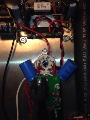
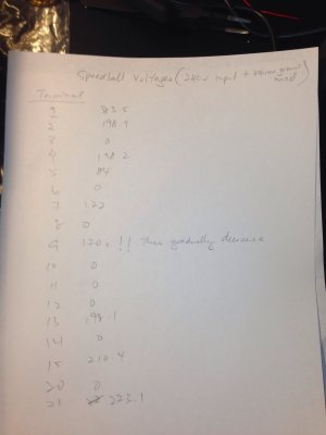
My Crack works ok before the installation of Speedball. After installation, the voltages appear fine except for terminal 9, which starts high (180s) and gradually decrease. Upon listening, the left channel is dead. :(

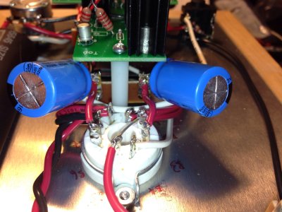
There were 2 incidents during voltage checks where there were sparks: the first time when the negative (black) test probe with alligator clip tester on terminal 12 came loose and touched terminal 13. In the second incident, I was shaking too much while testing terminal 7. ;) I shut down the amp right away. I hope I haven't short circuited anything.

Your help is much appreciated.
 
The experts are here soon to help, rest assured.
Just a thought, a short between B5 and B6? Happens for example if leads are too long, at the sockets they might rather easily shift. Pictures of the octal sockets solders and the adjacent termnal strip available?
 
Here are the photos of the octal socket and terminal 9. I've also attached the voltage readings.

Meanwhile, I'll reflow 9U.
 

Attachments

  • image.jpg
    image.jpg
    1.5 MB · Views: 103
  • image.jpg
    image.jpg
    1.6 MB · Views: 118
  • image.jpg
    image.jpg
    1.3 MB · Views: 101
Did an ohm check on terminals 7 and 9. Both appear to be increasing (charging) but the former is showing 6-ish mega ohms and climbing while the latter starts at 1ish. Not sure if this is normal. The test was performed after I've reflowed terminal 9. Near in mind I've done the grounding mod on the volume pot per the sticky thread in this forum.

Thanks for any suggestion you might have.
 
Try reheating the center leg of the TIP-50 feeding T9.

Also, just to double check, you did install the thermal pads and shoulder washers on the TIP-50's?

-PB
 
Caucasian Blackplate said:
Try reheating the center leg of the TIP-50 feeding T9.

Also, just to double check, you did install the thermal pads and shoulder washers on the TIP-50's?

-PB
OK I'll reheat the center leg for both TIP-50. And yup I've installed the clear thermal pad and washers.
 
Reheated the center leg of the TIP-50 closest to the volume pot on the right. A few seconds after switching on, both LEDs are now not working and there's some sparking under the PCB. I switched it off immediately. :(
 
Ok. What I'm going to do is to completely detach the main PCB and troubleshoot from there. How do I check to make sure the components are working, especially the TIP-50? Just resistance checks?
 
Hmm I'm not sure where the problem is under the PCB (right side of the picture). Here's a photo of the soldering job of the TIP-50.
 

Attachments

  • image.jpg
    image.jpg
    1.5 MB · Views: 113
  • image.jpg
    image.jpg
    1.3 MB · Views: 115
Ok. I've cleaned the board up anyway and tested the components via the back of the PCB. The components look ok.

Not looking forward to the voltage checks but I guess it has to be done.
 
I've put the PCB back after checking the soldering etc. No spars this time but unfortunately the same set of LEDs is still not lighting up. Should I attempt to replace them?
 
I'm not an expert here, but (per your last picture) it looks like small resistor is fried.
I hope PB can chime in soon to guide you a little further.
 
That's just the shadow from the flash I think. ;) here's a better picture.

Edit: just measured the resistance of that resistor. It's giving me a reading. I presume that if it's blown I won't be able to get a reading.
 

Attachments

  • image.jpg
    image.jpg
    1.4 MB · Views: 116
Back
Top