Hey Bottleheads,
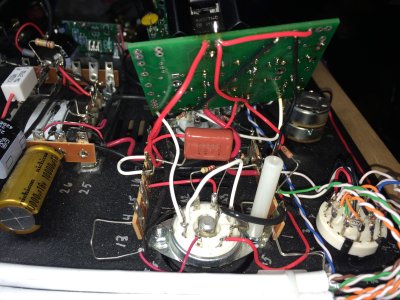
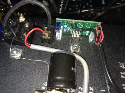
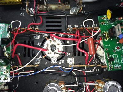
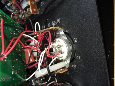
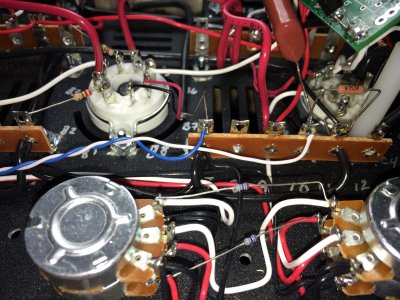
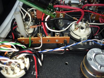
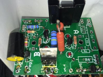
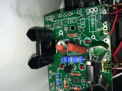
Unfortunately I'm back with another issue. After my smashup install, some of my voltages are way off. My kit is fully stock, and I will post photos shortly.
Here are some of my measurements. Thanks for taking a look")
Location/Socket A voltage/socket C voltage/voltage in the manual
The locations that were way off were noted with ********
IA/209.5/209.3/180-220
OA/207/207/150 ******
+regA/2.5/2.5/2.5
IB/207/206.7/150 *****
OB/64.9/65.3/45-75
KRegB/13.6/12.88/3-5 *****
BRegB/0/0/150 ******
+RegB/207.3/206/150 *****
Location/My measurement/Manuals measurement
B1/0/0
B2/207.2/150 ******
B3/13.6/3-5 *****
B4/0/0
B5/206.9/210
B6/12.9/3-5 *****
Unfortunately I'm back with another issue. After my smashup install, some of my voltages are way off. My kit is fully stock, and I will post photos shortly.
Here are some of my measurements. Thanks for taking a look
Location/Socket A voltage/socket C voltage/voltage in the manual
The locations that were way off were noted with ********
IA/209.5/209.3/180-220
OA/207/207/150 ******
+regA/2.5/2.5/2.5
IB/207/206.7/150 *****
OB/64.9/65.3/45-75
KRegB/13.6/12.88/3-5 *****
BRegB/0/0/150 ******
+RegB/207.3/206/150 *****
Location/My measurement/Manuals measurement
B1/0/0
B2/207.2/150 ******
B3/13.6/3-5 *****
B4/0/0
B5/206.9/210
B6/12.9/3-5 *****