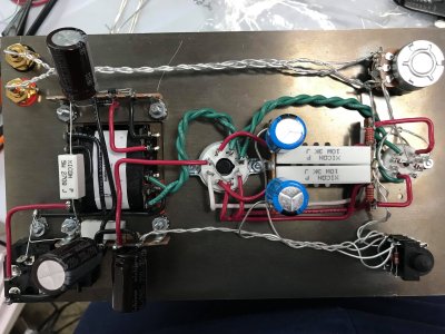
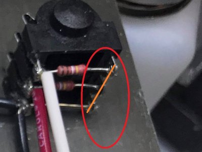
I'd check the manual for headphone jack. In the previous version of the crack the inner connections all went to lower outside ground. So in the new version of the wiring I would expect all of the outer lugs on the jack to be joined together. I could be wrong, but check the manual carefully.