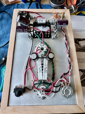
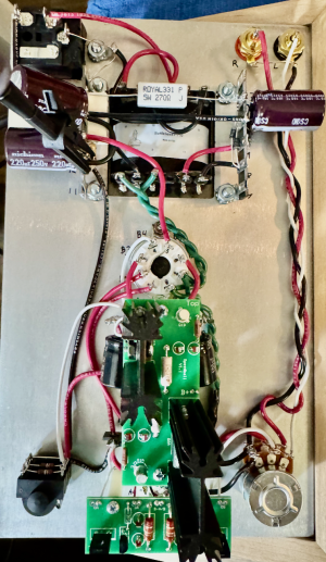
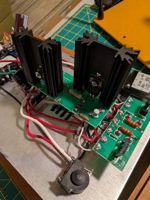
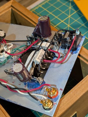
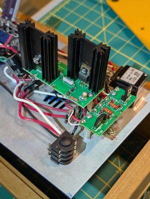
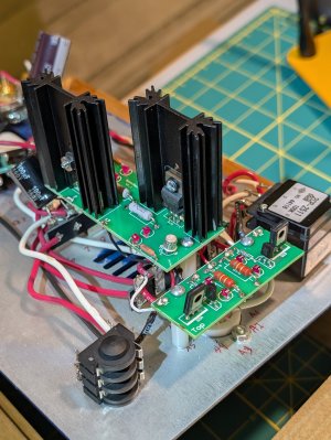
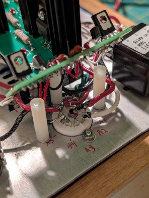
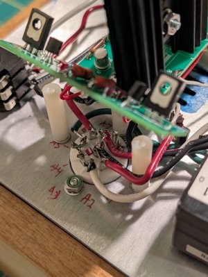
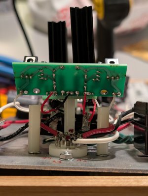
I just finished the assembly & installation of the Speedball. I ran the crack stock for about a month before starting the upgrade.
Small board installation went fine, and voltage checks passed within bounds. Large board installation resulted in voltages outside of the expected ranges (lb - OA +24%, lb - OB +16%) . Visual inspection and some cursory re soldering of suspected joints resulted in no change. Some simple tracing of connections resulted in consistent voltages back to the tube. So, could use any ideas. Mains voltage is ~120V.
Voltage checks post large board install (5 mins after plugging in to allow for stabilization):
Large board:
[list type=decimal]
[*]OA 123.8V
[*]OB 116.3V
[*]G 0.9mV
[*]B+ 183.2V
[/list]
Small board:
[list type=decimal]
[*]OA 86.4V
[*]IA 183.0V
[*]B0A/B 0.7mV
[*]IB 183.1V
[*]OB 94.2V
[/list]
Voltage checks post small board install: (tested and listened to after install per manual)
Small board:
[list type=decimal]
[*]OA 86.6V
[*]IA 171.9V
[*]B-A/B 0.9mV
[*]IB 171.7
[*]OB 93.4V
[/list]
And, for the sake of completeness, here are the voltage checks from when I finished the stock crack, before any of the speedball upgrades:
[list type=decimal]
[*]T01 88.7V
[*]T02 172.6V
[*]T03 0.9mV
[*]T04 172.6V
[*]T05 96.1V
[*]T06 0.7mV
[*]T07 111.3V
[*]T08 0.9mV
[*]T09 118.1V
[*]T10 0.7mV
[/list]
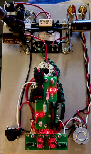
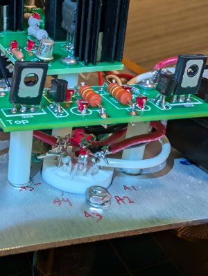
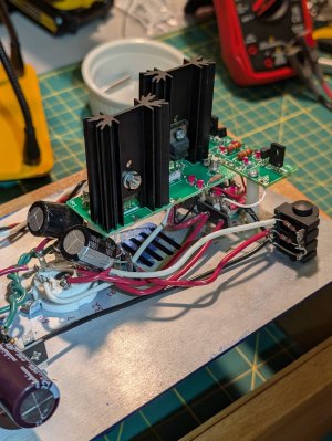
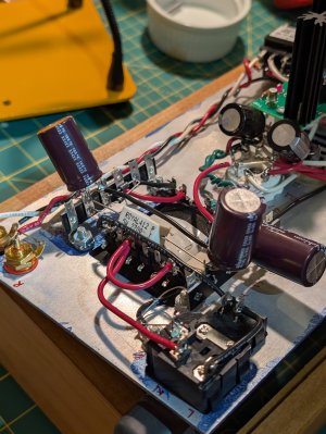
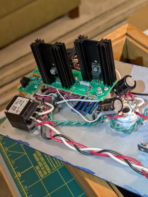
Pre and post install pictures attached.
Small board installation went fine, and voltage checks passed within bounds. Large board installation resulted in voltages outside of the expected ranges (lb - OA +24%, lb - OB +16%) . Visual inspection and some cursory re soldering of suspected joints resulted in no change. Some simple tracing of connections resulted in consistent voltages back to the tube. So, could use any ideas. Mains voltage is ~120V.
Voltage checks post large board install (5 mins after plugging in to allow for stabilization):
Large board:
[list type=decimal]
[*]OA 123.8V
[*]OB 116.3V
[*]G 0.9mV
[*]B+ 183.2V
[/list]
Small board:
[list type=decimal]
[*]OA 86.4V
[*]IA 183.0V
[*]B0A/B 0.7mV
[*]IB 183.1V
[*]OB 94.2V
[/list]
Voltage checks post small board install: (tested and listened to after install per manual)
Small board:
[list type=decimal]
[*]OA 86.6V
[*]IA 171.9V
[*]B-A/B 0.9mV
[*]IB 171.7
[*]OB 93.4V
[/list]
And, for the sake of completeness, here are the voltage checks from when I finished the stock crack, before any of the speedball upgrades:
[list type=decimal]
[*]T01 88.7V
[*]T02 172.6V
[*]T03 0.9mV
[*]T04 172.6V
[*]T05 96.1V
[*]T06 0.7mV
[*]T07 111.3V
[*]T08 0.9mV
[*]T09 118.1V
[*]T10 0.7mV
[/list]
Pre and post install pictures attached.