voltage check was about same as original check [resolved]

There could be a number of problems that would cause this kind of behavior, I'll try to list them all out:

1.  Either end of 249K resistor not well connected or the ground wire not well connected to that area.
2.  Backwards 1000uF cathode bypass cap.
3.  Miswire of the 220 ohm grid stopper from the 0.1uF cap/249K resistor to the 12 pin socket (the resistor is wired to the wrong tube pin).
4.  680 ohm cathode bias resistor is not well connected on one end or the wires on either end are missing or not well connected.
5.  Plate choke miswire.
6.  Shorted tube (this is why you'd want to test that tube on the other channel).

-PB
 
#1: Re-flowed, seemed well-connected
#2:1000 cathode cap attached same as in manual
#3: resistor connected to A 11,  not A 12.  connections appear solid
#4: re-flowed 680 ohm resistor.  appears well-connected
#5: PC-3 -  black is  heat-shrined ;  red unconnected but ready to be re-connected to 7 L;  Blue connected, re-flowed and appears solid to 10 L
#6: both tubes OK - assume when we switched tubes that was proved?
 
I would suggest borrowing a phone/digital camera to get some shots of the build.  There ought to be something touching that shouldn't be or something out of position on that side of the amp.

-PB
 
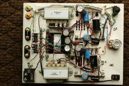
That's much easier to look at.  It looks like there's some kind of debris on the plate choke wires, is this just paint overspray?

Where the 1000uF cap lands, the two white wires heading there should connect to the terminal where the unbanded end of that cap connects.  If one of them is connected to the adjacent ground terminal instead, that would explain your problem except that the problem is still there with no tube.

I would check the red wire leaving terminal 10 to be sure it's connected to the correct pin on the 12 pin socket and that it's not touching anything else. 

If neither of these suggestions does anything, I would carefully remove the black Solen cap and post another photo so we can have a look at what's going on underneath.
 
1:  Yes it's paint

2:attached to 11 L are: one W wire from OT-2 #0 and one W wire from A-7

3: R wire from term 10 connects to  5A. The outside of the black cap may be landing on top of term 5 A.

4: Just found an obvious problem in the area - a blob of solder extended from the bottom of 10 L and touched the chassis plate.  Wonder how many times I have re-flowed and checked that area in the last few weeks.  One of those times I wish I had someone else to check after me.  Wishful thinking. I cleaned the offending blob outa there.
 
All voltages check out!  No fires!
Just hooked up the system.  Very fine sound.  Will start the upgrade after I enjoy some music for a while.
Thanks again for the patience and sage advice.
Looking forward to starting a phono amp kit next.
 
Back
Top