voltage check was about same as original check [resolved]

Dynakitbuilder

New member
The static in the R channel has increased to just about all the time set is on.  Can hear the static with both phones and speakers. L channel crystal clear.
 
If you knock on the chassis plate with your hand with some reasonable force, does that change the nature of the static?  Have you reflowed all of your solder joints?
 
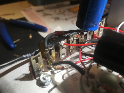
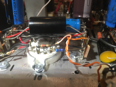
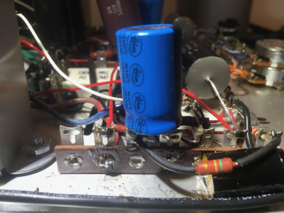
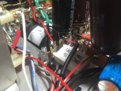
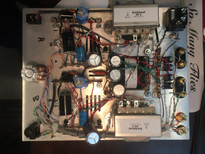
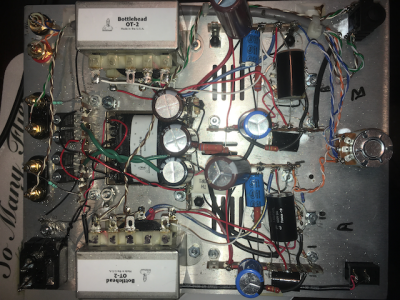
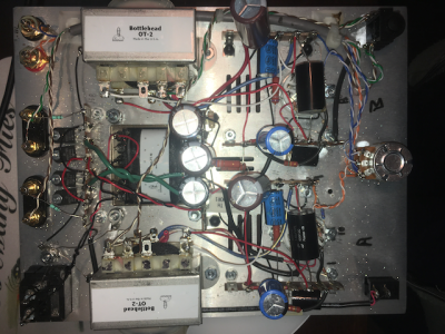
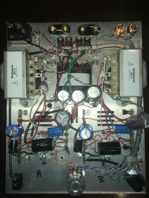
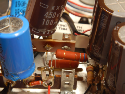
No effect with tapping on chassis.  Reflowed all solder joints.  Went back and reconfirmed all resistance checks - still the same readings.  Set up to do voltage checks; when I plugged in the amp, checked tubes glow; then the inside 680 ohm, 3w (blue, grey, brown, gold, pg 42 in manual)resistor started to smoke and turn red.  Unplugged set real quickly and started to call the fire department (not really); then after my blood pressure returned to somewhere near normal wrote this.  Assume the resistor is cooked, but don't understand why it went bad.  Did I overheat it during reflow?
 
That resistor will go bad because something is drawing excessive current.  You would want to start with a resistance check and posting any resistances that are off.  Also posting some build photos could be helpful too. 

If you soldered the joints on that resistor for 30-60 minutes, then maybe you could do some damage.
 
Thanks once again for the help and support.  Even with all this bit of hassle the whole experience had been a blast and convinced me to do other kits in the future.  I will post the resistances and photos. 
 
The files might be too large, data-wise. Try resizing them. If you use Windows, the default pic viewer gives you the option to resize to something suitable for email - I think it's max 2MB. That's fixed the problem of pics not uploading for me.
 
here's some photos: please let me know quality and quantity.  Trying to downsize photos to load better.
 

Attachments

  • IMG_1902.png
    IMG_1902.png
    493.9 KB · Views: 13
  • IMG_1903.png
    IMG_1903.png
    493.9 KB · Views: 7
  • IMG_1904.png
    IMG_1904.png
    537.8 KB · Views: 9
  • IMG_1905.png
    IMG_1905.png
    509.6 KB · Views: 9
  • IMG_1906.png
    IMG_1906.png
    534 KB · Views: 10
some with , some without flash
 

Attachments

  • IMG_1933.png
    IMG_1933.png
    596.7 KB · Views: 8
  • IMG_1932.png
    IMG_1932.png
    682.8 KB · Views: 3
  • IMG_1931.png
    IMG_1931.png
    637.1 KB · Views: 2
  • IMG_1930.png
    IMG_1930.png
    644 KB · Views: 5
  • IMG_1929.png
    IMG_1929.png
    604.6 KB · Views: 9
I would go ahead and do a voltage check on just that side of the amp.  That 680 ohm resistor is getting hot, but it's not smoking, so try to limit the amplifier on time to about 90 seconds. Once you perform those voltage checks, pull the 6FJ7 on that side of the amp and power it back up, then report the voltage on terminal 13.

It's still really hard to see much in those photos.  These photos are about 1/3 of a megapixel (a current cell phone is 48). 
 
I stopped buying "current" cell phones about 4 years ago.  74 years old.  Might not get my money's worth out of a new one.  I may be able to borrow a current phone from some neighbor that's not quite a luddite like me.  Will try.
 
Those are all still 640x480 images.

If you run the amp with no tube in the offending side, what's the DC voltage at terminal 13?
 
Can you reheat the solder joint at 7 and slip the red plate choke wire out, then leave it poking straight up in the air, then recheck the voltage at 13?
 
And just to be absolutely positive, if you take the tube that's out of the amp now and swap it with the tube that's still in the amp, does the low power supply voltage follow that particular tube?

What we learned by the voltage popping up when you removed the plate choke wire is that there's something connected on or around where the blue plate choke wire lands that shouldn't be there, or something is touching that shouldn't be, and that's dragging down the whole power supply and heating up the power supply resistor. 
 
Back
Top