Voltage check isn't checking out

brianbuntz

New member
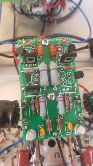
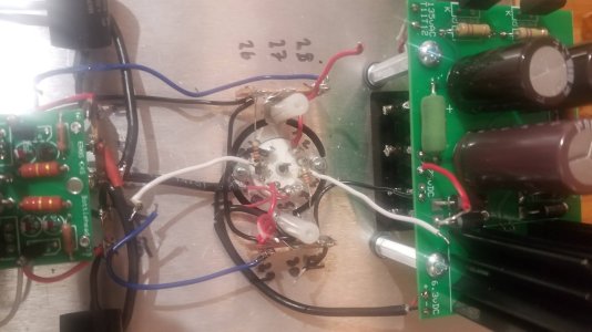
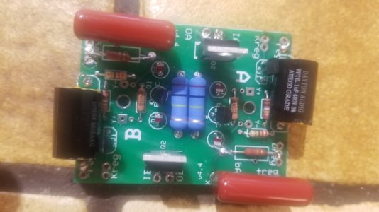
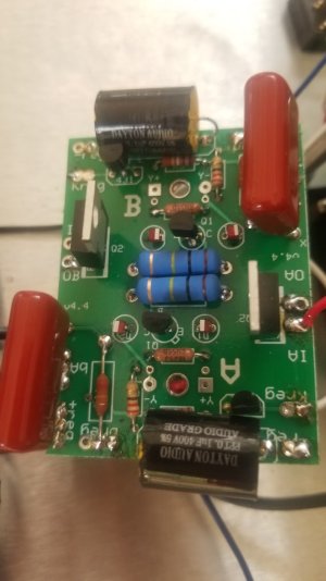
I just put together my kit and my voltages don't check out.  Here are my readings:
IA - 215
IB - 103
OA - 167
OB - 100
OC - 97
OD - 97
OkA - 99
OkB - 96
OkC - 1.8
OkD - 0
Thoughts?
 
Did the regulator board check out above the 12AU7 when you tested it? 

Posting build photos is really helpful for debugging.  Specifically the top and bottom of the main PC board and the wiring on the three front 9 pin sockets.
 
As far as I know, the regulator board is OK. All of the LEDs on that board come on, and the previous tests for the amp all checked out.

I may have had some touching leads on the bottom of the C4S board when I took a resoldered all of the connections on that board. Supporting that theory is a test I did with a semiconductor component analyzer, which suggested that two of the LEDs and one MJE350 had short circuits. I removed them and ordered replacements. 

I also found a potentially problematic solder joint for the resistor at RkA.
 

Attachments

  • 20200904_113922.jpg
    20200904_113922.jpg
    154.6 KB · Views: 21
  • 20200904_113915.jpg
    20200904_113915.jpg
    177.7 KB · Views: 15
I would not have removed any parts from the amp.  I can't even remember the last time I had a bad MJE-350...

When you have all the parts on the board that should be there, let us know and we can continue looking for what's going on.
 
OK, Here it is again.

For now, seem to be having the same issue. I haven't done the voltage check again because I have a couple of LEDs that are not coming on. If all of the LEDs are not on, is it safe to check the voltages again?
 

Attachments

  • 20200912_114656.jpg
    20200912_114656.jpg
    175 KB · Views: 18
brianbuntz said:
For now, seem to be having the same issue. I haven't done the voltage check again because I have a couple of LEDs that are not coming on.
Voltages are informative.  LEDs glowing or not glowing isn't particularly useful information on its own.


brianbuntz said:
If all of the LEDs are not on, is it safe to check the voltages again?
Yes, please check the voltages.
 
OK, Here are the readings. Not sure why there is 0 Volts on OkD. IB and OB are off as well.

IA - 215V
IB - 103V
OA - 167V
OB - 101V
OC - 96V
OD - 99V
OkA - 97V
OkB - 98V
OkC - 1.7V
OkD -  0V
 

Attachments

  • 20200912_154130.jpg
    20200912_154130.jpg
    96.1 KB · Views: 6
Pop the wires out of IA and IB on the board up front mounted above the 6922 tube, then recheck operation of the board above the 12AU7 using the instructions at the end of page 55 in the manual.
 
Retested:  216 on the B side and 141 on the A side.  This is different than my previous test, so I guess the build doesn't pass.  Assuming I should remove my board and check all connections.
 
Yeah, there's an issue with the regulator above the 12AU7.  Look for broken wires, joints that aren't soldered on the terminal strips mounted by the 12AU7, etc.

If you can't locate anything wrong, you could certainly post pictures of that area and we can have a look to see if we can spot anything.  This part of the circuit has to work 100% before debugging the rest.
 
OK, that board had checked out OK, so it is possible there was a bad solder joint or something. I reflowed solder in most places. Here's where I am now:
 

Attachments

  • 20200913_091004.jpg
    20200913_091004.jpg
    280.3 KB · Views: 14
  • 20200913_091034.jpg
    20200913_091034.jpg
    261.5 KB · Views: 17
  • 20200913_091029.jpg
    20200913_091029.jpg
    262.6 KB · Views: 11
If you look at R1 on the A side, see how we can see down into the board around one lead of the resistor?  That's a textbook solder joint that hasn't been heated enough.  The solder needs to flow through the plating on the inside of the holes on the PC board.  I would reheat all your joints and heat them until you see the solder suck down into the joint.

The one exception to this would be the solder joints for the LEDs, as generally there is so little material to heat with the LEDs that the solder joints flow almost instantly.
 
OK, I reflowed the solder in all of the joints on that board. Also reflowed the solder in the tube socket below. 

The voltage of the MJE5731A on the A side is still measuring too low -- about 140V. It is correct on the B side. Don't know what else to try.
 

Attachments

  • 20200913_133900.jpg
    20200913_133900.jpg
    98 KB · Views: 19
So, from your photos I can tell that you added solder from the top side of the board.  That's not really my recommended approach.

One of your R2 resistors has a similar solder joint that looks insufficient.  Please try reheating these from the bottom side of the board, all the joints.  You don't need to add solder from the top side.
 
Hi there. I added solder from the bottom, but added a little extra on top. Maybe that wasn't necessary.

Anyway, the problem is likely not the solder joints but one of the 2.49k Ohm resistors. I went through checking all of the resistors and the one on the A side read 7.3 Ohm. It still has the right color - red, yellow, white, brown, brown. Going to order a new one and swap it out and see what happens.   
 
Or it could be the TL431 transistor that has two legs across that resistor.

In either case, there will be an associated cause with that failure, and not finding the cause may lead to repeated destruction of whatever part is no longer in spec.
 
So the 431 transistor has a short circuit according to a tester I have.

Re: what might be causing it to short, I don't know. I went through all of the instructions this morning again, reflowed solder everywhere and performed all of the tests indicated in the manual and it passed everything up until this step.
 
Back
Top