Voltage check failure: Terminal 7 reads 154 VDC, not 170-230 VDC

jmittan

New member
Hi all,

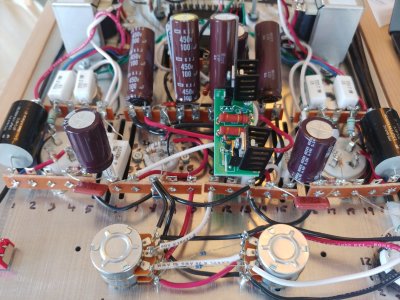
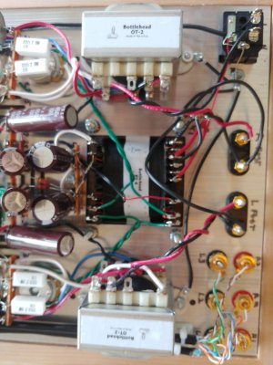
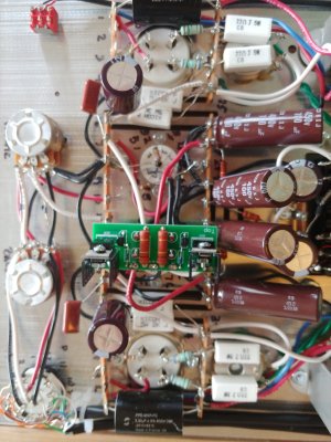
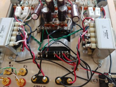
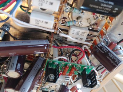
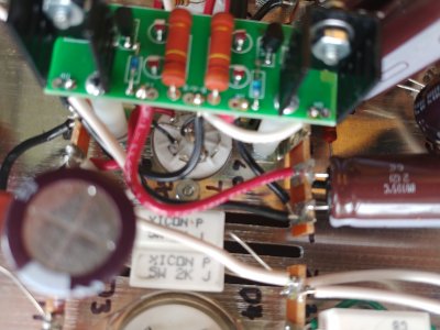
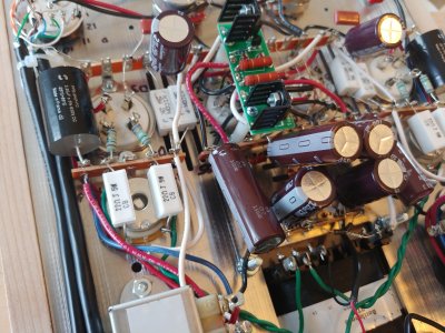
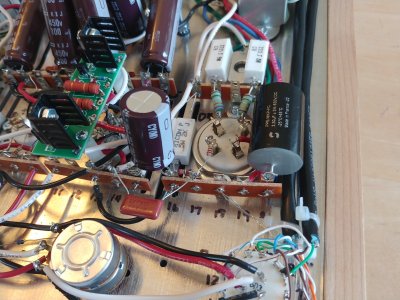
First time poster. I completed my build of the Stereomour II. After doing my voltage check, I identified a failure. Terminal 7 reads 154 VDC, not the correct 170-230 VDC. However, Terminal 14 reads 179 VDC correctly. I did notice the LEDs on the side with the lower reading of the PCB are lit more dimly than the side with the correct reading.

What could be causing the drop in VDC? Does a voltage of 154 to the 12AT7 tube have negative impact (other than an imbalance of sound)?

Thanks!
 

Attachments

  • 20230314_111501.jpg
    20230314_111501.jpg
    415.5 KB · Views: 9
  • 20230314_111446.jpg
    20230314_111446.jpg
    309.8 KB · Views: 6
  • 20230314_111438.jpg
    20230314_111438.jpg
    352.8 KB · Views: 7
  • 20230314_111513_HDR.jpg
    20230314_111513_HDR.jpg
    354.6 KB · Views: 3
Thanks for identifying the incorrect position of PN2907! I was able to detach the transistor and reattach it in the correct position. I am now getting a reading of 203 VDC at terminal 7. However, now I read 0 VDC at terminal 14. This time the LEDs on the other side of the PCB are lit dimly. Why would this be the case?
Thanks!
 
Can you post a photo of the build in that area?  0V at terminal 14 would make me suspicious that one wire isn't hooked up to the PC board.
 
Thanks! Here are some photos.
 

Attachments

  • 20230314_134233.jpg
    20230314_134233.jpg
    5.1 MB · Views: 5
  • 20230314_133212.jpg
    20230314_133212.jpg
    263.1 KB · Views: 4
  • 20230314_132953.jpg
    20230314_132953.jpg
    418.1 KB · Views: 5
  • 20230314_132937.jpg
    20230314_132937.jpg
    425.5 KB · Views: 3
  • 20230314_133114.jpg
    20230314_133114.jpg
    383.7 KB · Views: 4
  • 20230314_133205.jpg
    20230314_133205.jpg
    394.2 KB · Views: 7
You can pop the wires out of IA, IB, OA, and OB, then rotate the board 180 degrees and reinstall it to see if the voltage problem moves to terminal 7 (which would indicate an issue on the PC board) or stays put at terminal 14 (which would indicate an issue around the socket wiring or terminal strips).
 
I think I found the problem. One of the leads (closest in the photo attached) appears to have broken. Not sure how to resolve this. Do I solder a blob from the top of the PCB to reconnect?

Thanks!
 

Attachments

  • 20230314_135525.jpg
    20230314_135525.jpg
    2.5 MB · Views: 29
Thank you! much appreciated. I was able to "graft" a cut lead through the through-hole onto the lead of the MJE5731A and solder all together. Terminal 7 reads 203 and terminal 14 reads 184. Though it is now +-15 VDC on the other side, at least it is in the recommended range of 170-230.

cheers!
 
Those are certainly reasonable values.  If one used plate loading resistors in place of the C4S, you could pin those voltages down a lot tighter, but in this circuit that plate voltage deviation doesn't particularly matter.
 
Thanks. I'm curious. What plate loading resistors would you suggest?

According to another messaging board post “a plate supply resistor should be more than 3 times the plate resistance at your chosen operating point (plate voltage, current, grid voltage), and should drop between half and 2/3 of the supply voltage for best linearity, leaving the other 1/2 to 1/3 of the supply voltage for the tube.” Is this true? Then what would the plate loading resistor values would I use to get the 170-230 VDC? Would I connect the various wires to plate loading resistors? If so, red and black in and white out, instead of the C4S?

Thanks again for your help resolving my issues!

 
Using a resistor plate load for the 12AT7 driver will increase its distortion substantially - that is, after all, the reason we use current source loads!

That said, the appropriate resistor would be 33K. It should be rated 3 watts or more, and 400 volts or more.
 
Back
Top