hifiDane
New member
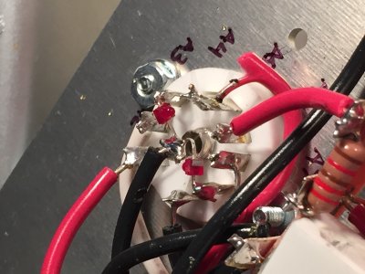
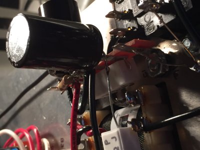
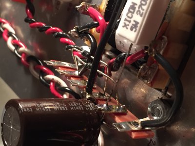
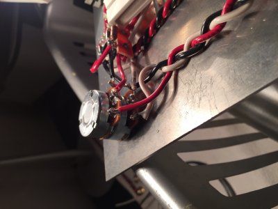
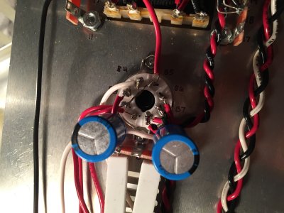
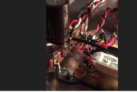
Hey folks, I need some help. Resistance check passed but I am having some trouble with voltage check. I have gone through the manual and followed ever wire to make sure that it is in its proper location. I have checked every solder joint and re-heated and added a bit of solder to every joint.
Here are the terminals that aren't checking out for me on my voltage check:
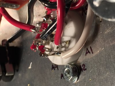
2 - 90V (should be 170V)
4 - 90V (should be 170V)
7 - 6.4mV (should be 100V)
9 - 4.3mV (should be 100V)
13 - 90V (should be 170V)
15 - 245V (should be 185V)
B2 - 90V (should be 170V)
B3 - 6.1mV (should be 100V)
B5 - 90V (should be 170V)
B6 - 4.1mV (should be 100V)
Both tubes light up.
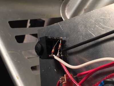
Neither of the LED lights turn on.
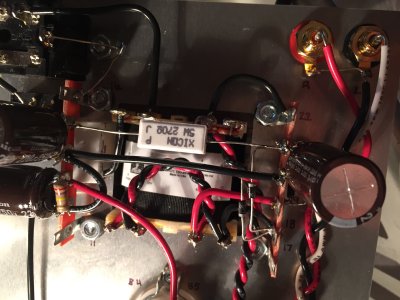
Also, I checked the AC on transformer and it was not reading the 150V value specified on the label but lower at 90V.
Thanks in advance!
Here are the terminals that aren't checking out for me on my voltage check:
2 - 90V (should be 170V)
4 - 90V (should be 170V)
7 - 6.4mV (should be 100V)
9 - 4.3mV (should be 100V)
13 - 90V (should be 170V)
15 - 245V (should be 185V)
B2 - 90V (should be 170V)
B3 - 6.1mV (should be 100V)
B5 - 90V (should be 170V)
B6 - 4.1mV (should be 100V)
Both tubes light up.
Neither of the LED lights turn on.
Also, I checked the AC on transformer and it was not reading the 150V value specified on the label but lower at 90V.
Thanks in advance!