Audiotechyo
New member
Greetings, I have had my Crack kit for a while and really, really enjoy it. Being a young electrical engineer I just can't help but want to experiment with it, some things I am interested in trying are as follows.
1) add a pre-out from my crack at the pre-amp stage, this pre-out would then be passed through a unity gain buffer stage in order to ensure that as little energy from the actual signal is used. I am trying to keep my crack from changing its sound in any way if I can.
2) potentially also take this new signal and add an active filter to cut off the low end so I can have a sub out since I have a nice powered sub right below my desk.
3) while I dont think adding this will give me literally any real accurate information I would like to add a VU-Meter I salvaged from a busted TEAC Tape Deck years ago. I have tested this VU-Meter and it does indeed still function when I hook it up to my powersupply. (Needles move up and down)
With this I also have the intention of hooking it up via a unit gain buffer stage.
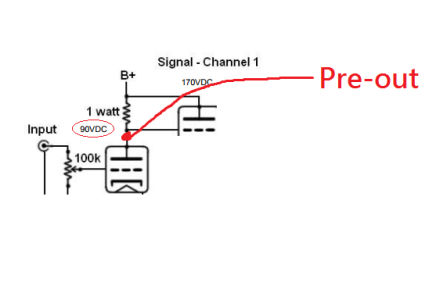
So my question is, from my understanding, the pre-amplifier stage of the amp ends at the bottom of the 1watt resistor on the given schematic that I dont think I am allowed to post here. The schematic says this point will be 90Volts DC, which I assume means I will have to use a cap to remove the DC part of the signal and then I should get what I want.
I am still new to EE so please let me know if I have solid understanding of whats happening or if I am missing some key points. I really have worked very little with amplifiers, the two stage small signal transistor amplifier I designed in college wasn't without a lot of help and although I think I grasp how it works, I dont have a scope at my disposal to check things.
1) add a pre-out from my crack at the pre-amp stage, this pre-out would then be passed through a unity gain buffer stage in order to ensure that as little energy from the actual signal is used. I am trying to keep my crack from changing its sound in any way if I can.
2) potentially also take this new signal and add an active filter to cut off the low end so I can have a sub out since I have a nice powered sub right below my desk.
3) while I dont think adding this will give me literally any real accurate information I would like to add a VU-Meter I salvaged from a busted TEAC Tape Deck years ago. I have tested this VU-Meter and it does indeed still function when I hook it up to my powersupply. (Needles move up and down)
With this I also have the intention of hooking it up via a unit gain buffer stage.
So my question is, from my understanding, the pre-amplifier stage of the amp ends at the bottom of the 1watt resistor on the given schematic that I dont think I am allowed to post here. The schematic says this point will be 90Volts DC, which I assume means I will have to use a cap to remove the DC part of the signal and then I should get what I want.
I am still new to EE so please let me know if I have solid understanding of whats happening or if I am missing some key points. I really have worked very little with amplifiers, the two stage small signal transistor amplifier I designed in college wasn't without a lot of help and although I think I grasp how it works, I dont have a scope at my disposal to check things.