I ran through the resistance checks and terminals 22 and 23 aren't giving the correct values. They should be *, fluctuating value, but instead when I probe each, the multimeter doesn't even respond to the probe. I tried re soldering all the immediate wire connected to the terminal and rechecked that those wires were in the right place. All the other resistance checks are good, just these two. Appreciate any help.
You are using an out of date browser. It may not display this or other websites correctly.
You should upgrade or use an alternative browser.
You should upgrade or use an alternative browser.
Troubleshooting Resistance Checks
- Thread starter ksolis01
- Start date
No response is consistent with the note provided for the asterisk. 22 and 23 are your incoming line voltage, so not getting any resistance reading there is a good thing.
The voltage checks provide infinitely more information than "the LEDs don't glow".
Got them.Caucasian Blackplate said:The voltage checks provide infinitely more information than "the LEDs don't glow".
Terminal Voltage (DC)
Low Current C4S
IA 150V (187.6)
OA 60-90V (79)
KregA 3-6V (1.947)
bRegA 150V (188)
IB 150V (148)
OB 60-90V (55.2)
KregB 3-6V (13.04 )
bRegB 150V (148.1)
High Current C4S (D socket)
IA 190V (192)
OA 150V (148)
bA 0V (0)
IB 0V (0)
OB 90-110V (82.5)
bB 150V (148.1)
High Current C4S (B socket)
IA 190V (188)
OA 150V (186.9)
bA 0V (0)
IB 0V (0)
OB 90-110V (0.025)
bB 150V (0.044)
Headphone Jack
Tip 0V (0.01)
Ring 0V (0.04)
bB ties to OA with a red wire. bB is 0.044V, OA is 186.9V. They are not connected.ksolis01 said:Low Current C4S
IA 150V (187.6)
KregA 3-6V (1.947)
bRegA 150V (188)
OB 60-90V (55.2)
High Current C4S (B socket)
OA 150V (186.9)
OB 90-110V (0.025)
bB 150V (0.044)
Ok, soldered that connection again. These are the only two value that change significantly and were the problems ones. They seem within range but the two leds I mentioned in my previous post still didn't turn on.Caucasian Blackplate said:bB ties to OA with a red wire. bB is 0.044V, OA is 186.9V. They are not connected.
High Current C4S (B socket)
OB 90-110V (95.9)
bB 150V (186)
Recheck all your voltages. bB isn't going to be 186V without one of the Kreg voltages being off. Also, bB should be extremely close to 150V. (within a volt or two)
KregA and and KregB are significantly off, especially B.Caucasian Blackplate said:Recheck all your voltages. bB isn't going to be 186V without one of the Kreg voltages being off. Also, bB should be extremely close to 150V. (within a volt or two)
Terminal Voltage (DC)
Low Current C4S
IA 150V (187.7)
OA 60-90V (79.3)
KregA 3-6V (1.936)
bRegA 150V (187.7)
IB 150V (148.1)
OB 60-90V (54.6)
KregB 3-6V (12.9)
bRegB 150V (148)
High Current C4S (D socket)
IA 190V (190.5)
OA 150V (148)
bA 0V (0)
IB 0V (0)
OB 90-110V (81.4)
bB 150V (148.1)
High Current C4S (B socket)
IA 190V (188.3)
OA 150V (186.7)
bA 0V (0)
IB 0V (0)
OB 90-110V (96.5)
bB 150V (186.5)
Headphone Jack
Tip 0V (0.01)
Ring 0V (0.04)
I would suggest flipping over the high current C4S board with the troubling voltages and reheating all of the solder joints on that board, as well as the socket under it.
This builder had similar issues that ended up being resolved by reheating the solder joints, with particular emphasis on the center leg of each MJE5731A.
This builder had similar issues that ended up being resolved by reheating the solder joints, with particular emphasis on the center leg of each MJE5731A.
Ok, I reheated all the joints. However, when I connected it, something under both high current C4S boards started to smoke. Immediately disconnected it. On the B socket, the 237Ω 1/8 W resistor connecting B5 to B6 got burnt. On the D socket both 220Ω 1â„4W connected to the ground lug intertwined got burnt.Caucasian Blackplate said:I would suggest flipping over the high current C4S board with the troubling voltages and reheating all of the solder joints on that board, as well as the socket under it.
This builder had similar issues that ended up being resolved by reheating the solder joints, with particular emphasis on the center leg of each MJE5731A.
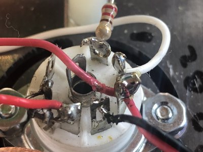
Can you show me pictures of that area on your amp. Neither of those parts is under any thermal stress whatsoever, but a short on or around the socket could cause damage like this.
Hopefully this is enough photos. First 9 are the B socket. The rest are D socket
Attachments
-
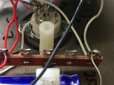 Photo May 26, 12 30 28 PM.jpg1.2 MB · Views: 13
 -
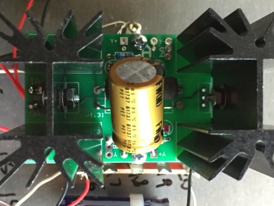 Photo May 26, 12 27 58 PM.jpg469.3 KB · Views: 0
 -
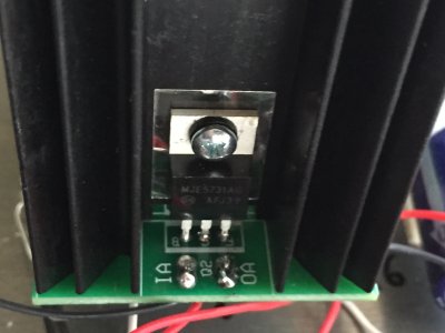 Photo May 26, 12 28 10 PM.jpg766 KB · Views: 0
 -
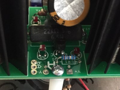 Photo May 26, 12 29 06 PM.jpg763.6 KB · Views: 0
 -
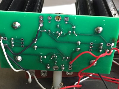 Photo May 26, 12 29 54 PM.jpg1.2 MB · Views: 4
 -
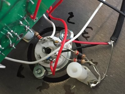 Photo May 26, 12 30 05 PM.jpg920 KB · Views: 7
 -
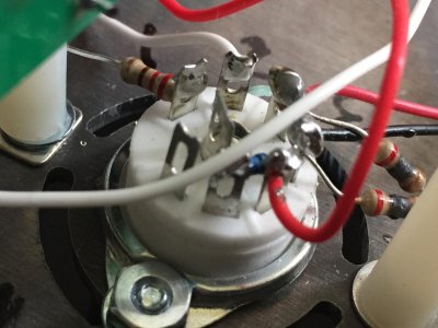 Photo May 26, 12 30 10 PM.jpg456.6 KB · Views: 10
 -
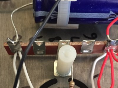 Photo May 26, 12 30 20 PM.jpg831.9 KB · Views: 2
 -
 Photo May 26, 12 30 28 PM.jpg1.2 MB · Views: 3
 -
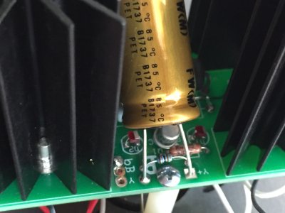 Photo May 26, 12 27 47 PM.jpg808.4 KB · Views: 4
 -
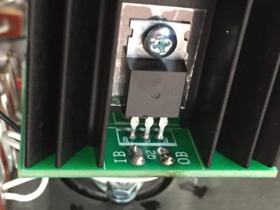 Photo May 26, 12 27 34 PM.jpg835.7 KB · Views: 3
 -
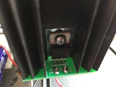 Photo May 26, 12 23 40 PM.jpg1,023.3 KB · Views: 7
 -
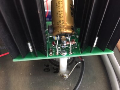 Photo May 26, 12 23 49 PM.jpg1.2 MB · Views: 7
 -
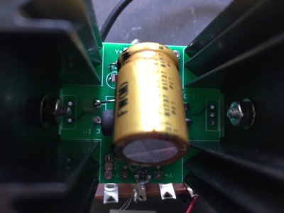 Photo May 26, 12 24 03 PM.jpg1.3 MB · Views: 1
 -
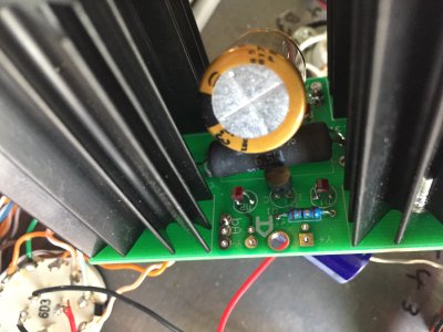 Photo May 26, 12 25 42 PM.jpg1.4 MB · Views: 1
 -
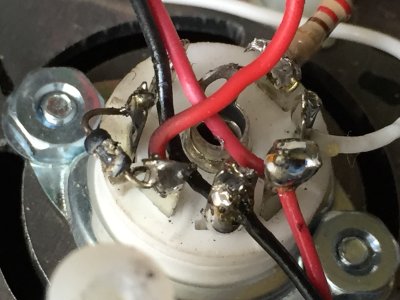 Photo May 26, 12 26 12 PM.jpg1 MB · Views: 9
 -
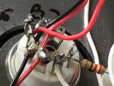 Photo May 26, 12 26 31 PM.jpg1,012.3 KB · Views: 8
 -
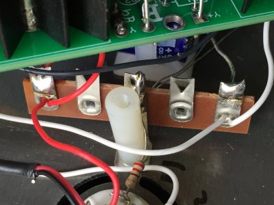 Photo May 26, 12 26 46 PM.jpg1.3 MB · Views: 3
 -
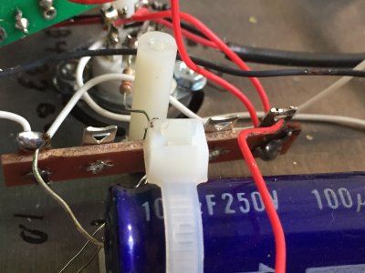 Photo May 26, 12 27 03 PM.jpg1.2 MB · Views: 1
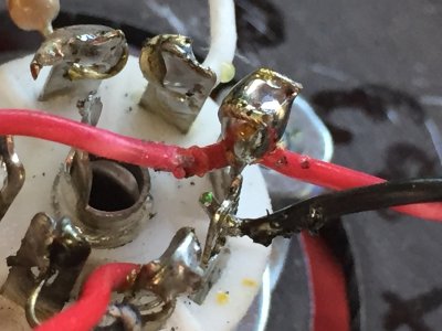
I would wonder if the tube socket lug where the 237 ohm resistor connects got shorted to the black wire next to it.
Is this the wire provided with the kit?
Is this the wire provided with the kit?
Ye, the whole build is stock. Going to wait on getting the new resistors and then recheck all related wiring to try to find how the short happened.Caucasian Blackplate said:I would wonder if the tube socket lug where the 237 ohm resistor connects got shorted to the black wire next to it.
Is this the wire provided with the kit?
Hmm, peculiar. It appears that the B+ supplying the plate at pin 5 of socket B shunted current thru the 237 ohm resistor between 5 and 6. Somehow the 237 ohm resistor been shorted to the heater winding, thus also taking out the resistors on pins 3 & 4 of the D socket, which tie from heaters of both socket B and D to ground, and thus would be the path to ground for the short.
So the question is how did the screen at pin 6 in socket B get shorted to the heater winding (pins 3 and 4 on both B and D)?
So the question is how did the screen at pin 6 in socket B get shorted to the heater winding (pins 3 and 4 on both B and D)?
Got the replacement resistors today. I checked around that area and when I was resoldered that area to try to get rid of any bad solders, I melted off the rubber on quite a bit of the heater wiring. The first two are pictures of the black heater wire in the B socket. My wiring ended up pretty tight, and the desoldered black wire part nearest to the end (first two pictures) was resting on B5 terminal. I'll fix it tomorrow, and am just posting along with pictures to confirm that this is probably the cause. Don't want to connect it tomorrow and end up shorting the resistors again.Doc B. said:Hmm, peculiar. It appears that the B+ supplying the plate at pin 5 of socket B shunted current thru the 237 ohm resistor between 5 and 6. Somehow the 237 ohm resistor been shorted to the heater winding, thus also taking out the resistors on pins 3 & 4 of the D socket, which tie from heaters of both socket B and D to ground, and thus would be the path to ground for the short.
So the question is how did the screen at pin 6 in socket B get shorted to the heater winding (pins 3 and 4 on both B and D)?
To fix this, would it be fine to solder on a bit of extra length using leftover white wire or some of the black and red wire from leftover heater wire and wrap electrical tape on all the exposed areas? The extra wire to loosen up the area and decrease the chance that something rest on something.
Attachments
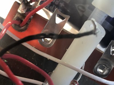
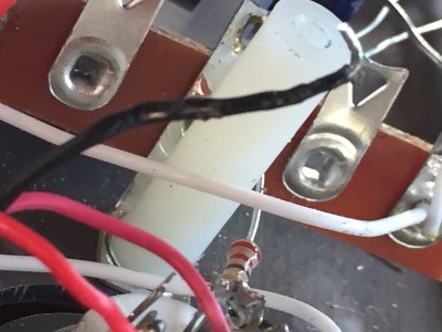
In order to fry that screen resistor on the 7 pin tube socket, you would either have to have a freakish short inside the tube that would've damaged other parts, or the pin and/or screen resistor leads had to be touching one of the heater leads.
I taped up all the possible ends that could have caused the short and added the burnt resistors back. I went through all the voltage test and essentially got the results that I got before, the little variation was within the decimals. I already tried resoldering all the connection under the problem board. Just gonna resolver again I guess.
ksolis01 said:KregA and and KregB are significantly off, especially B.
Terminal Voltage (DC)
Low Current C4S
IA 150V (187.7)
OA 60-90V (79.3)
KregA 3-6V (1.936)
bRegA 150V (187.7)
IB 150V (148.1)
OB 60-90V (54.6)
KregB 3-6V (12.9)
bRegB 150V (148)
High Current C4S (D socket)
IA 190V (190.5)
OA 150V (148)
bA 0V (0)
IB 0V (0)
OB 90-110V (81.4)
bB 150V (148.1)
High Current C4S (B socket)
IA 190V (188.3)
OA 150V (186.7)
bA 0V (0)
IB 0V (0)
OB 90-110V (96.5)
bB 150V (186.5)
Headphone Jack
Tip 0V (0.01)
Ring 0V (0.04)