yorkmichael
New member
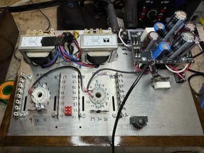
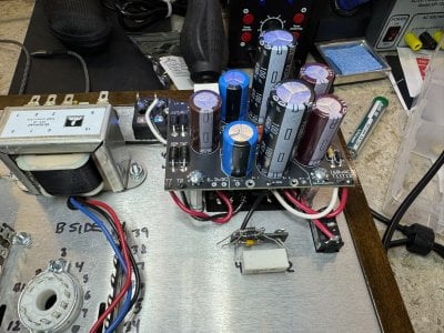
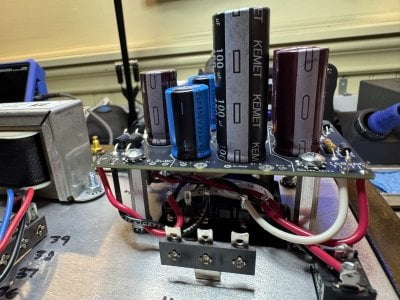
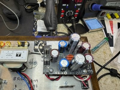
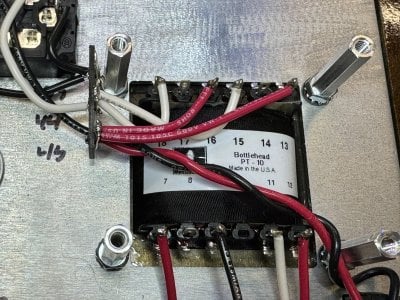
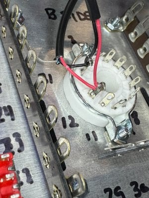
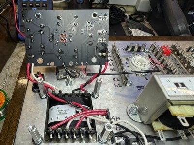
I'm building a S.E.X. 4 Kit and ran into a problem during the tube glow test right after installing the tube heater circuit (page 74). When I connected the amp to power during the glow test, the tubes did not glow and after about 20 seconds I could smell smoke coming from the power transformer. I unpowered the amp immediately and waited for the B+/B++ voltages to drop before inspecting further. There is no sign of any kind of miswiring. No obvious location of a short circuit. I removed the tubes and tried to power the amp once again to test the transformer voltages. I'm not getting voltage readings off the transformer (terminal 7 and 9 or terminal 11 and 12), but I am still getting 470+ VDC off the B+/B++ voltages off the terminals on the PCB (with multimeter ground on Terminal 40). I'm not getting any voltage off the 6.3VDC terminals. The only thing I can think of is the dangling wires from the OT transformers might have shorted something during the tube test (but no sign of this with blackened wires or components). Of course, it's possible I also mis-wired the heater circuit, but it doesn't appear like I did as far as I can tell. If I mis-wired something and need to replace the power transformer out of pocket, then that's ok - expensive lesson learned (as long as I can figure out what I did wrong, so I actually learn something).
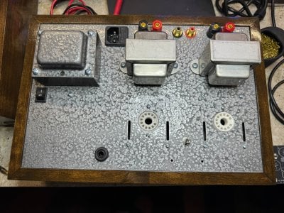
I'm attaching pics of my build thus far so someone can inspect the wiring and hopefully spot where I might have made a mistake. I'm 99% sure the transformer is blown - but is there a definitive way to verify? If there's a proven way to test the power supply circuit board assembly to validate this incident didn't damage any other components that would be helpful too.
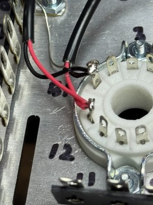
Note for the pic of the heater wiring - it may at first appear like I wired it backwards. I accidentally clipped the black wire in the 7" three-conductor wire bundle a bit too short (page 72). Since the instructions on page 72 said "it does not matter which wire goes into which hole" I wired the black wire into the left hole on the 6.3vDC terminals but the other end of the black wire is attached to B1. This is consistent with the instructions (the left 6.3V terminal is connected to B1 and the right is connected to B12. I also noted in the instructions, B1 was connected to A12 and B12 was connected to A1. I connected the same way but swapped the red and black wires to be consistent. It should be electrically identical to the instructions - just with the red insulation swapped with the black insulation.
I'm attaching pics of my build thus far so someone can inspect the wiring and hopefully spot where I might have made a mistake. I'm 99% sure the transformer is blown - but is there a definitive way to verify? If there's a proven way to test the power supply circuit board assembly to validate this incident didn't damage any other components that would be helpful too.
Note for the pic of the heater wiring - it may at first appear like I wired it backwards. I accidentally clipped the black wire in the 7" three-conductor wire bundle a bit too short (page 72). Since the instructions on page 72 said "it does not matter which wire goes into which hole" I wired the black wire into the left hole on the 6.3vDC terminals but the other end of the black wire is attached to B1. This is consistent with the instructions (the left 6.3V terminal is connected to B1 and the right is connected to B12. I also noted in the instructions, B1 was connected to A12 and B12 was connected to A1. I connected the same way but swapped the red and black wires to be consistent. It should be electrically identical to the instructions - just with the red insulation swapped with the black insulation.