Hi,
Could anybody offer some advice please, I'm just a novice builder!
I'm in the UK and these are my readings after finishing my build:
RESISTANCE:
1 - 2.48
2 - 2.42
3 - 0
4 - 2.56
5 - 2.45
6 - 0
7 - 1.11
8 - 0
9 - 1.11
10 - 0
12 - 0
13 - 2.50
14 - 0
20 - 0
22 - 0
B3 - 1.11
B6 - 1.11
Center pin - 2.23
Ground tab - 0
VOLTAGE:
1 - 84
2 - 192.5
3 - 0
4 - 192.3
5 - 83.6
6 - 0
7 - 114.2
8 - 0
9 - 114.9
10 - 0
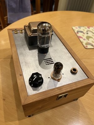
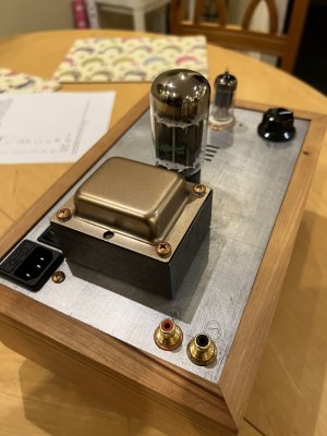
Both led's have lit up.
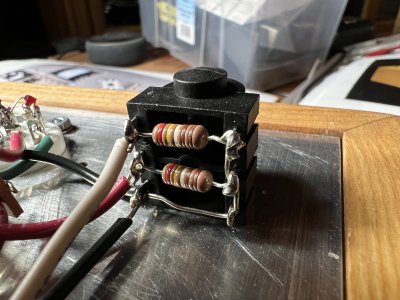
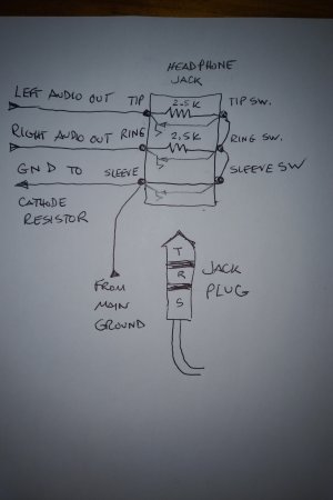
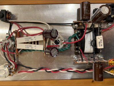
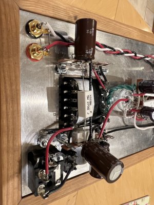
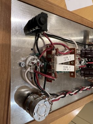
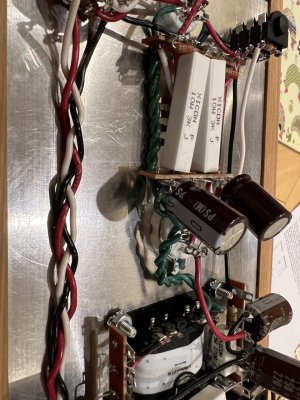
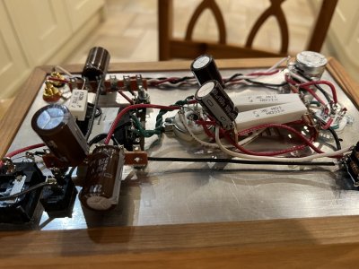
When I insert headphones the 6080 tube flashes and I get a shock from the metal.
Is there anything obvious that I have done wrong? My soldering looks okay but I'm no expert!
I've attached some pics.
Any help would be very much appreciated.
Could anybody offer some advice please, I'm just a novice builder!
I'm in the UK and these are my readings after finishing my build:
RESISTANCE:
1 - 2.48
2 - 2.42
3 - 0
4 - 2.56
5 - 2.45
6 - 0
7 - 1.11
8 - 0
9 - 1.11
10 - 0
12 - 0
13 - 2.50
14 - 0
20 - 0
22 - 0
B3 - 1.11
B6 - 1.11
Center pin - 2.23
Ground tab - 0
VOLTAGE:
1 - 84
2 - 192.5
3 - 0
4 - 192.3
5 - 83.6
6 - 0
7 - 114.2
8 - 0
9 - 114.9
10 - 0
Both led's have lit up.
When I insert headphones the 6080 tube flashes and I get a shock from the metal.
Is there anything obvious that I have done wrong? My soldering looks okay but I'm no expert!
I've attached some pics.
Any help would be very much appreciated.
Attachments
-
 Screenshot 2022-03-23 232212.jpg470.9 KB · Views: 24
 -
 thumbnail_IMG_0135.jpg330.8 KB · Views: 18
 -
 thumbnail_IMG_0136.jpg303.6 KB · Views: 20
 -
 thumbnail_IMG_0137.jpg190.7 KB · Views: 19
 -
 thumbnail_IMG_0138.jpg265.3 KB · Views: 22
 -
 thumbnail_IMG_0140.jpg248.1 KB · Views: 11
 -
 thumbnail_IMG_0141.jpg245.3 KB · Views: 12