Speedball upgrade fail - please help

What are the OA/OB values on the small board? 

How much rotation are you using on your volume pot?  They can be a bit imbalanced at low volume levels, and a mod for this is provided in our FAQ.
 
I just measure again:
Small board;
OA: 63V
OB: 77V

Large board:
OA: 107V
OB: 99V

I use the volume pot at around 10 - 2 o'clock. The imbalance is consistent throughout the range.
My headphone is ZMF Aeolus, rated at 300 ohms.
 
Yeah, there's a reasonable difference on the plates of the 12AU7, and since the circuit is directly coupled, this also appears on the 6080.

These are DC differences though, the AC performance of the circuit will not show such large differences.
 
I use the volume pot at around 10 - 2 o'clock. The imbalance is consistent throughout the volume range.
My headphone is ZMF Aeolus, rated at 300 ohms.

It's really not a big deal since I can use APO equalizer. However, if needed what can I do? Do you think the volume pot mod can correct it?
 
If the pot is all the way up, is the channel imbalance still there?  If so,  I would be most suspicious of a solder joint issue in the amp. 

Can you post a photo of your small Speedball board installed in the amp?
 
Other than the LEDs, those joints could use a bit more solder and more heat.  You want to see the solder wick through the holes to the other side if possible.  The LEDs have such low thermal mass that the soldering process is really quick, and that's why they look good compared to the other joints.

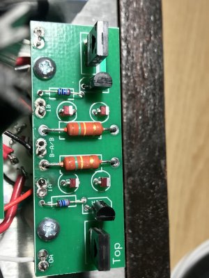
If you look at the photo you posted, notice that the solder joint on Q1A closest to the 237 ohm resistor looks like it has no solder in it.  You'll want to heat up that joint till the solder flows through the hole. 

As far as the channel imbalance goes, if it's present with the volume pot all the way up and it's more than a dB or two, then there's likely a solder joint in the amp that's not behaving.  You could also try different tubes, though a bad tube will usually make itself known with problematic voltages.
 
I always solder the top side as well as the bottom. From other pictures around the forum this doesn't seem to be the norm. The topside usually only needs a very small amount of solder to make a good meniscus around the component leg to finish the joint. The wire connections here look as if the solder has hardly flowed at all, very dry and dirty. You can prop up the wire with a folded up tissue , or anything really, to stop the wire dropping out when you heat the joint.
 
I have check and re-solder to make sure the joints have enough tin. The problem still persists.
However, I wonder if a blown capacitor can affect voltage. One of my capacitor looks like this.
 

Attachments

  • IMG-2385.jpg
    IMG-2385.jpg
    428.9 KB · Views: 28
Those caps feed both channels, so you won't get one low channel if there's an issue with that cpa.  That one is a little domed out at the top, what's your incoming AC line voltage and which range have you used when building the Crack?  That cap sees the lowest voltage and the least ripple current compared to the other 3, so it would be a bit strange to see something like that.

 
Back
Top