I'm just glad that its looking like the whole thing isn't toast!
Also: there is only one LED on the octal. I had some short/issue a little while back and I followed the advice on a post in this forum that swapped out a jumper for the 2nd LED (which worked).
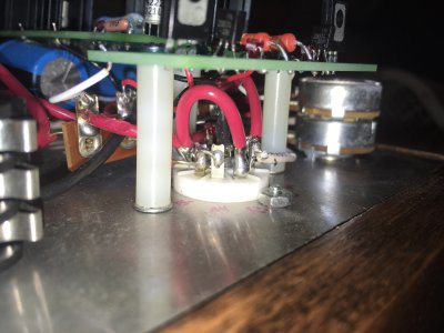
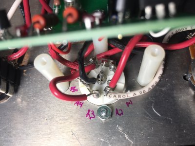
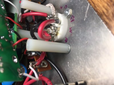
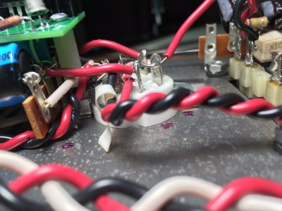
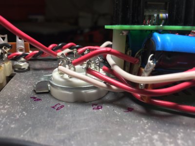
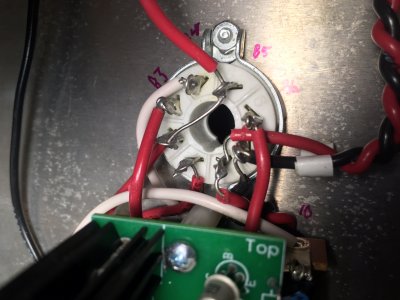
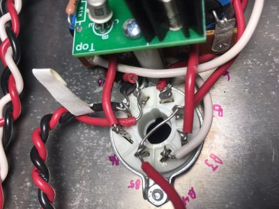
PB is looking for pics of the other socket. Octal= 8 pins, Noval= 9 pins.
Sometimes photos can be deceptive but check that the jumper you put in on the Noval socket is not shorted to pin 7.
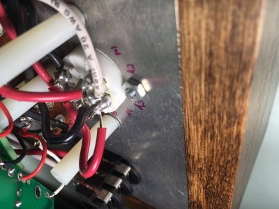
That will give you all sorts of grief. In general you should not have that much uninsulated wire exposed. pin a2 is the way they should be.
Of course, thank you, that socket does have 9 pins not 8!
The jumper is currently not shorting to the 7th pin. I went ahead and wiggled the tube all around the noval and it doesn't appear that any wire is touching nor able to touch its neighbor.
I will pick up some liquid insulator and shore up those exposed bits asap though, thanks for the tip.
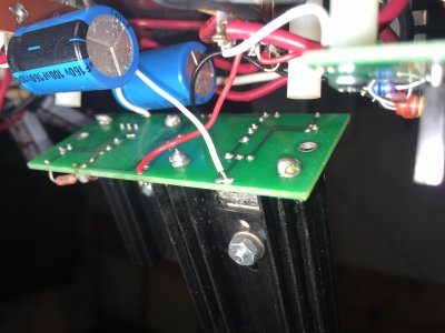
It's totally possible that the big board just didn't survive the flux event. What is the DC resistance to ground that you get from OA and OB on the big PC board?
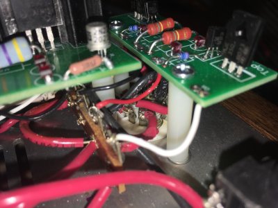
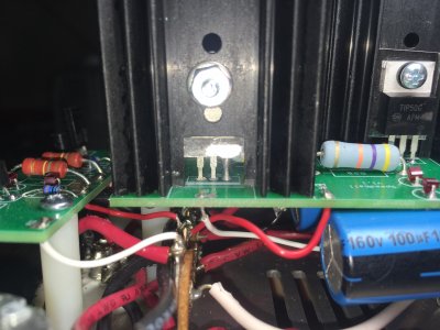
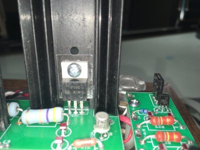
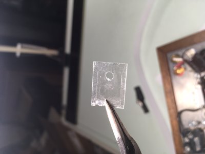
Yeah, I would double check that the mounting hardware is properly installed. If the metal tab of the TIP50 is allowed to contact the heatsink, you will get the issue you're having.
I checked the TIP50 assembly, took it apart and reassembled; it had been assembled correctly. The insulator looks pretty beat up, probably from the wash, with some dents but looks intact (pic attached).
I went ahead and reflowed the TIP connections, then reflowed everything I could reasonably reach on the big board.
You could carefully power it up and see if the rail voltage stays up above 150 or tanks down like it has been. That issue that only comes up with the 6080 installed and a 0 ohm resistance at OA or OB on the PC board does point to a transistor installation problem or another slight possibility is a shorted or backwards 100uF cap.
Success! Thanks so much for bearing with a novice.
All the rail readings were 182v.
The 60 and 124 OA and OB resistance readings from yesterday were in mV (if I am reading my multimeter correctly).
As the OA resistance is still low at 60, should I be attentive to anything in particular going forward?
And would the flux that I used periodically need to be scrubbed from the connections (IE does it continue to sweat out from the solder points as the points are exposed to heat over time?).
Can you double check the DC voltages at terminals 7 and 9? With 182V of B+, the voltages at 7 and 9 are likely either correct or one of them is now 0.
If the flux returns, another round through the dishwasher would be called for, though I can't recall ever having to perform that task twice on the same kit.
Oops, I didn’t mean to jump to a premature resolution! The LEDS were all lit up and I listened to a record without problem before seeing your last response.
DC voltages:
7: regular bounce between 105 and 111v
9: regular bounce between 102 and 108v