Speedball Troubleshooting - High OA/OB values

Justin

New member
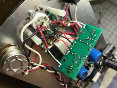
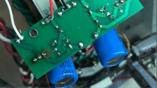
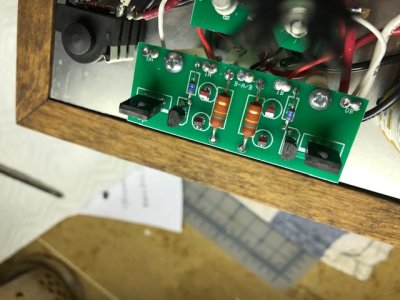
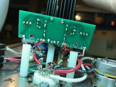
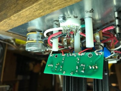
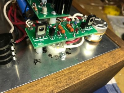
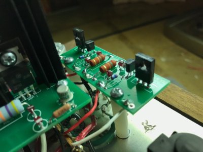
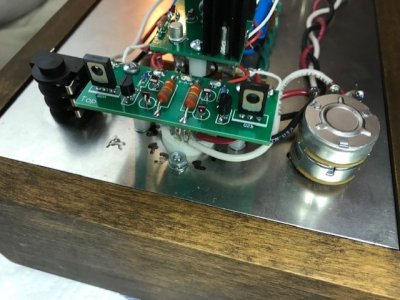
Hi, forum. I'm currently putting a Speedball together and ran across a snag I'm hoping to get some help with. I previously built an tested the Crack which worked well, was in spec and sounded impressive. I installed the small board for the Speedball and after some troubleshooting I realized I installed the MJE350s the wrong way. Before fixing this I was getting readings of:
OA - 0
1A - 202
B-A/B - 0
1B - 203
OB - 0

After correcting the orientation of the MJEs I remeasured and am currently at:

OA - 144
1A - 162
B-A/B - 0
1B - 162
OB - 137

All LEDs light up. When I follow the diagnostic flow chart I'm hitting a dead end where it tells me to check voltages at A2 and A7 - both values in my kit are below 1 volt. I've re-soldered anything on the board that looked remotely sketchy. Anything obvious I'm missing that would explain the high OA/OB numbers?

Justin


Would it be possible for you to post some photos of your board?  If you can unscrew the screws that hold it down, you should be able to take a photo of the top and bottom without pulling it out of the circuit.
 
Sure, see attached.

FYI the middle lead of one of the MJEs broke when I was removing them to fix the orientation but I feel like I was still able to get a decent connection when I re-soldered it to the board. I don't think that's causing my problem but who knows.
 

Attachments

  • IMG_0010.jpg
    IMG_0010.jpg
    663.2 KB · Views: 16
  • IMG_0005.jpg
    IMG_0005.jpg
    519.1 KB · Views: 14
  • IMG_0007.jpg
    IMG_0007.jpg
    524.5 KB · Views: 9
  • IMG_0010.jpg
    IMG_0010.jpg
    663.2 KB · Views: 8
  • IMG_0011.jpg
    IMG_0011.jpg
    612 KB · Views: 12
I think I see some of the board trace that has come off in this photo.  This can happen without the proper tools if you try to pull the transistors.  To be honest, I would contact replacement parts about just getting a new small board plus parts, as this one is likely beyond being salvaged.
 

Attachments

  • crack trace.jpg
    crack trace.jpg
    260.6 KB · Views: 36
Hi Paul. So I ordered a replacement board (got it lightning quick btw, like 3 days quick!) and after I reassembled and installed both boards I'm getting similar readings on the little board along with high readings at OA and OB on the bigger board.

Little Board:
OA - 155
1A - 184
B-A/B - 0
1B - 184
OB - 140

Big Board:
OA - 150
OB - 160
G - 0
B+ - 184

All LEDs light up although the ones on the little board are dim. The amp works and sounds incredible. These numbers are clearly out of range - any ideas what might be causing them? Just let me know if you need any more photos.

-Justin

 
Please don't listen to an amp that doesn't pass its voltage checks, it can damage your headphones and potentially cause bodily harm.

Can you pull the 6080 tube and measure just the small board with the 12AU7 installed?

 
Okay, thanks for the advicel.

The values on the small board with the 6080 pulled are:

OA – 150
1A – 228
B-A/B – 0
1B – 229
OB - 135
 
Yeah, its the one that came with it. I just substituted a different 12au7 from another amp and got 111V OA and 115V OB on the big board. You think that was it?

 
No, there's a bigger underlying issue here.

Can you post some new photos of the top and bottom of the current small PC board? 


Do you still have the 22K resistors that you removed when installing the small PC board?
 
I appreciate the help.
 

Attachments

  • thumbnail_IMG_0047.jpg
    thumbnail_IMG_0047.jpg
    84.3 KB · Views: 7
  • thumbnail_IMG_0046.jpg
    thumbnail_IMG_0046.jpg
    74.9 KB · Views: 7
  • thumbnail_IMG_0045.jpg
    thumbnail_IMG_0045.jpg
    94.5 KB · Views: 9
  • thumbnail_IMG_0043.jpg
    thumbnail_IMG_0043.jpg
    90 KB · Views: 11
  • thumbnail_IMG_0042.jpg
    thumbnail_IMG_0042.jpg
    74.8 KB · Views: 11
  • thumbnail_IMG_0048.jpg
    thumbnail_IMG_0048.jpg
    88 KB · Views: 11
I would go back to the 22K resistors instead of the small PC board, then continue debugging the circuit.  The issue you're experiencing is likely something iffy with the underlying build.
 
Oooookay. New 22.1K resistors in place of the small board. I retraced every step in the instructions from point to point (I'd be surprised if it were miswired at this point but foolish to rule it out), and carefully inspected and re-soldered any joint that I didn't like. During this process I found a couple of wires i'd attached to a lower terminal that i went ahead and corrected to the upper as the instructions called for or visa versa, but nothing that I think would affect the current. Right now my resistance and voltage terminal checks are as follows:

Resistance    Voltage
1. *                131.5V
2. *                186
3. 0                    0
4. *                184.5
5. *                124.7
6. 0                    0
7. Over Limit  144
8. 0                    0
9. Over Limit  140
10. 0                  0
12. 0
13. *
14. 0
20. 0
22. 0
B3. Over Limit
B6. Over Limit
RCAs in spec

I can provide any other measurements or pictures as necessary. Any ideas?


I am going to guess that your LEDs on the 9 pin socket aren't lighting.  When you look at the 12AU7 with the amp on, do both halves of the tube glow?
 
Back
Top