Speedball small board voltage higher by factor of 2 [resolved]

mferring1

New member
Built standard Crack. All voltages good, ran for the last month and a half with no issues.

Started building Speedball. Ran into a problem.....

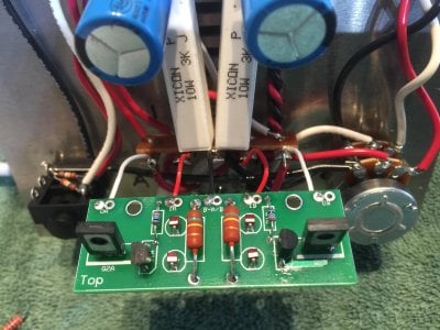
All LEDs on (2 9 pin socket and 4 on small board), went thru the troubleshooting flowchart leg for OA or OB above 110 and all checks out OK. However, my voltages are off by a factor of 2 at all 4 small board locations.

That is, OA "and" OB are around 150, not 75ish..........And IA "and" IB are around 380, not 190ish.

BTW, B-A/B is zeroV

This seems to imply something that is common to the whole board and not a particular solder connection or component (since the entire board has this problem).

Any thoughts as to what might be affecting these voltages by a factor of 2? Is it possible that the 12AU7 tube has a problem?

Mark Ferring
 
If your using the same tube that you have been using it's not logical that it would be the problem. Check that you have the correct resistors in each position.
 
Thanks for the reply Doc. I appreciate you helping with this.

Yes, I do believe that I have the resistors in the correct position. Here is a picture.
 

Attachments

  • IMG_0872.JPG
    IMG_0872.JPG
    740.8 KB · Views: 123
What is funny to me is that I am getting both the same 2X factor on both the A and B side. So either there is a common single issue, or I made the same mistake on both sides.
 
Looks OK on the top. Do you have both tubes installed when you are doing the voltage check? Heaters glowing? Do the LEDS on the nine pin socket light? Sure you are grounding your black test lead at T12?
 
Just to be sure, I did it again.....

Both Tubes installed?        Yes

Heaters Glowing?              Yes

LEDS on Nine Pine Socket light?      Yes

Grounding black test lead at T12    Yes

For full disclosure, I did have the PN2907 on the B side installed backwards initially. I swapped that around and the picture is where we currently are. I did power up the amp with the PN2907 in that backwards configuration. Not sure if that would possibly have any effect......

Mark Ferring
 
You can measure resistance between each possible pairing of the three transistor leads and see if any read shorted, i.e. like less than 50 ohms. However it does not seem likely that a problem with one 2907 would affect both channels. And if all of the LEDs are lighting my hunch would be that either the voltage measurement itself is inaccurate for some reason or the R1 resistors are not correct or not soldered in well, creating too little current draw thru the tube and thus elevated voltages. They appear to be the right value in the photo. You might want to measure their resistance just to be sure.

Maybe if we could see a picture of the underside of the board we could spot something.
 
Measured both R1 resistors without power and they read ~245 ohms.

Attempted to reflow all four solder joints for the R1 transistors.

Re measured Voltage: Same.

Few pix of the back....

Darnnnnn
 

Attachments

  • IMG_0873.JPG
    IMG_0873.JPG
    583.4 KB · Views: 114
  • IMG_0874.JPG
    IMG_0874.JPG
    1.7 MB · Views: 109
OK the resistors seem to be in the ballpark. Maybe try a different DC voltage range scale on your meter to see if the voltages read about the same. Sometimes meters can read weird on one range setting and fine on another in certain circuits. You might also reflow all of the connections at terminal 3. That connection is common to both channels. One possibility I can think of is that the connection of the big white ceramic resistors has gone cold from the new connections made at T3, and that means the 6080 is not conducting properly. Since this is a circuit where the two tubes are directly connected that could pull the 12AU7 and small board voltages way off.
 
Just reflowed the T3 and re measured. I used two different voltmeters and two ranges on each. Still the same voltages....

I will say that for a short period after I noticed the PN2907 was backwards, the voltages were in the appropriate range. I thought all was well at that point. Then after I desoldered  and rotated the transistor to the proper location, the voltages were wrong again. So there might be something simple here. But heck if I know what it is. I have checked and rechecked all the circuit connections and reflowed most of them already. Fairly frustrating at this point of course!

Happy to try anything else. It simply looks like it should work at this point.....
 
OK, I don't have a good theory for why the pn2907 would affect both channels. Let's try to avoid yanking out parts until other less invasive things are tried. Could you measure voltage at terminals 7 and 9? That will help give us some idea of the functionality of the 6080.
 
This may be clutching at straws, but it also looks from the underside shots like possibly one leg of the removed and reversed pn2907 might not be going all the way thru the hole. You might just reflow those 2907 connections one more time, paying attention to how the solder pulls in around the pads.
 
My logic on this is that the only thing that has been physically disturbed in the connections of the 6080 during the small PC board installation is terminal 3, where the big cement resistors that determine that current and voltage connect to ground. Sorry to keep coming back to this but a bad solder joint at T3 seems the most likely candidate if the 6080 is installed correctly and it glows when you power on. There are four things connected at  terminal 3 - a black ground buss wire that goes from the volume pot to 3L, the black wire from the center terminal of the nine pin socket to terminal 3L, the black wire from the B- pad on the little PC board to terminal 3U, and what would seem to be the potential problem, the twisted leads of the 3K 10W cement resistors inserted into terminal 3U.

Power off, unplug from the wall socket and a wait for a couple of minutes. Then try measuring resistance from terminal 7 to terminal 12 and terminal 9 to terminal 12. Should be a little under 3K for each one if that connection at T3 is solid. You might try wiggling the resistors at the T3 end gently to see if you can make the meter jump around.
 
No worries coming back to the same thing. I get your logic completely and am happy to keep trying things. I really like following any leads that would have potential voltage effects on both the A and B side.  I have built a few kits in my day, but I have tremendous respect for your history and experience. I will gladly follow any lead you suggest.

To that end, unfortunately, T7 and T9 were both in the 2930-2500 Ohm range. I wiggled the big cement resisters around (and every other wire going into T3) and could not get the reading to change.

Quick question. One of the leads on each of the 237 Ohm resistors is really close to one of the leads of the 2907 transistor. Are there any potential issues if the solder on those two joints touch each other? I don't think they do but my old eyes are having a hard time telling (and this is adding my reading glasses to my driving glasses for extra magnification!).

One other quick question for the learned master......I don't remember the math from my old engineering circuits class 40 years ago, but is there any single place in the circuit where a bad connection or component could cause this almost  perfect doubling of all the voltage readings?

 
Can you power the amp back up and measure A3 and A8? should be around 1.5-1.6VDC.


OK, let's take a small sideways step. Carefully check the AC volts across power transformer terminals 4 and 5, which supply the heater current. Should be around 6.3VAC. Just want to verify the meter calibration.

If that is OK, I think maybe it is time to consider replacing the PN2907 that was in backwards. I don't have an exact scenario in my head of how one 2907 would throw both sides off and pull the cathode LEDS up from 1.56V, but that should more or less take you back to where things went haywire.

Another thing you can try is pulling the 6080 and remeasuring DC voltages OA, OB and A3 and A8. I don't imagine they will change, but it might give some more info.
 
Maybe one more step before replacing the 2907 -

I keep coming back to T3 connections being the culprit. One more reflow of all the connections on T3 might be worth trying. If that doesn't help you might want to try temporarily disconnecting IA/IB, OA/OB and reattaching the original 22K resistors to verify that voltages go back to normal. That would narrow the issue down to the board itself and not the ground connections.
 
Back
Top