Sound faded away from one channel / High voltage readings on Crack [resolved]

kattjaevel

New member
Hi! When I first completed my Crack resistances and voltages checked out when measured, but after a while the sound in the right channel faded out.

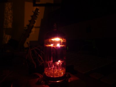
Now when I measure the voltages I get some weird values. Between 12 and below points it's higher than expected. The A8 LED doesn't light up, nor does the topmost side of the 12AU7 glow
A6 145V,
B1 145V,
B3 145V

Any clues where to start figuring this out?
 
Do both halves of the 12AU7 glow?  Can you very carefully measure the DC voltages at A3 and A8?

Often times an issue like this is the solder joint at A4/A5.  If it's not well connected, half of the 12AU7 will be extinguished and you will get all of these symptoms. 
 
No, the filament attached to A8 doesn't glow.

I went over and redid the solder points at A4 and A5... They looked OK before but perhaps a bit better now. A4 doesn't have the best physical contact. However, they measured 0 Ohm impedance to ground before and after.

A3 measures 1.6V, A8 measure -1.0V DC...

Edit: I switched to the original 6080 (Apparently I had used another I had laying around) and with it, one of the sides does not glow as much as the other.
 
some images:

u3oGAeR.jpg

FxSfPo2.jpg

WbAKOKy.jpg

 
1.  Power transformer terminal 9 has a wire going through it that almost touches power transformer terminal 10.  If those should ever touch, you will blow fuses endlessly until you trim that.
2.  Are both black wires captured by solder where they meet on the headphone jack?
3.  Is the wire that connects to A4/A5 passing through A4?  It looks like perhaps not?
 
Thanks Paul for the feedback!

I trimmed the cable at 9, was about 3mm of gap but it wouldn't be nice blowing a fuse during all of this. Resoldered the black wires at the headphone jack (they looked OK before). The wire goes through A5 and bends up at A4 so it locks in place. I had some more time today so will attach some more pictures that might be helpful. Starting the project a few years back I was using a really poor soldering iron (very big tip and wasn't heating properly at the tip) and had matching skills. So lots of joints look dirty. Is that something that could cause issues and I need to redo?

YcfS5gY.jpg

fHG84QM.jpg

BMR3KAe.jpg

x1EdQVO.jpg

wtvmAm5.jpg

fZn4XFZ.jpg

TUd9Pyn.jpg
 
Remember if your iron isnt heating properly, you need to keep the tip clean before using, by rubbing on a wet sponge and using some flux....if you dont keep it clean you
will not get good heat at the tip needed for proper soldering.

Also sometimes the tip can become loose and needs to be tightened in the heating element....

I mention this because you stated having issues with heating and the tip...

Alex
 
kattjaevel said:
I bridged A3 and A8 and still no action with the A8 connected filament.
So no change in voltage at terminals 1 and 5?

kattjaevel said:
Is my tube bad?
There's about a 1/1,000 chance that your tube is bad.  There's a 999/1,000 chance that there's a bad solder joint, broken wire, etc. in the amp causing this problem.  This is based on your information that one channel just kind of faded off on its own.  If maybe the 12AU7 was dropped or something was dropped on the amp, then the channel dropped, that would be different.  When a tube goes from good testing to bad testing, it doesn't just turn off immediately.  There will be a period of a few thousand hours where things just don't sound right before things get so ugly sounding that you go looking for what's wrong.

Can you tell me if both halves of the 12AU7 glow?  I asked before and I think you thought I was referring to the LEDs. 
 
No, the upper side of the 12AU7 still doesn't glow. That's what I tried explaining when I wrote that the filament doesn't glow. Probably incorrect terminology. This kit is very old if that adds to it. I bought it some 7-8 years ago.

T1 reads 145V,
T5 reads 92V
 
Inside the 12AU7 there are two plate structures.  Each plate structure has a heater that runs up the middle.  You may be able to see the bottom of each heater structure and/or the top of each heater structure.  If you can't see glowing dots on the top of each plate structure, then you need to look at the bottom of each plate structure to see if you have a glowing dot on each side.

If you have two glowing dots on the bottom of the tube, then that's useful information.  If you aren't sure, consider posting a photo of your tube glowing in a dark room.
 

Attachments

  • tube glow.jpg
    tube glow.jpg
    59.7 KB · Views: 8
Sorry Paul, I see how my response may be unclear. I see that the heater closest to the front of the chassis, the one that sits on top of A3, glows. But the one that sits on top of A8 doesn't.
 
What is a good way of testing that? Visually they look similar, not one that is pulled out further or anything. When I look at them from the top I can see both sockets look just like the others.
 
I redid the soldering on A4/A5, as well as B7/B8 (both from the transformer and from B to A). I can with confidence say that these connections shouldn't be an issue any longer. I made sure that they were solid and didn't move a millimeter before soldering and made sure to solder properly. Redid voltage readings. Still the "left" side of the board measure too high. Here are some outstanding values...

T1: 140V
T2: 160V
T4: 160V
T5: 95V

T7: 140V
T9: 108V

A6: 140V

B1: 140V
B3: 140V
 
Do both halves of the 9 pin tube glow?  If not, and you're confident that your connections are good, I would replace the 12AU7.  If the new 12AU7 has one half that doesn't glow, then you will need to go back over those heater connections.
 
Back
Top