Solved - Paramount - Low Volume very muffled

Horatio

New member
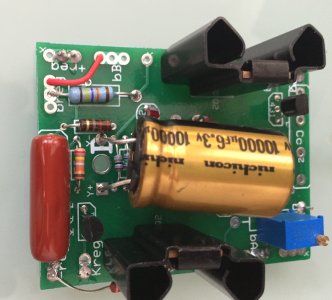
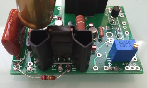
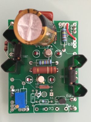
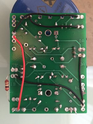
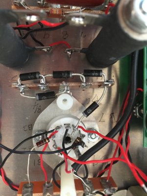
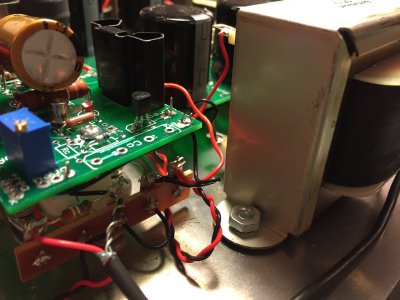
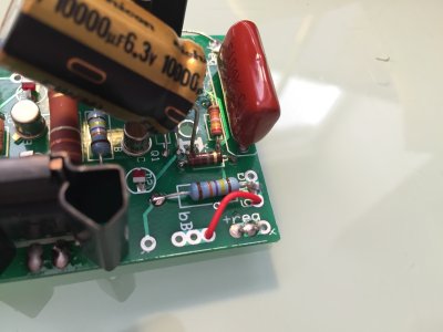
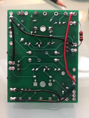
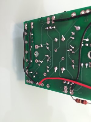
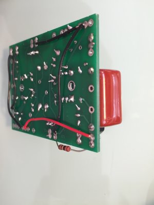
Hi, just finished my Paramount kit build and am having a few challenges... The some of the voltage / resistance checks don't look right and the upshot is that while the Paramounts turn on, both tubes light up, the sound that comes out of my Orca speaker is of a very low volume, very muffled and somewhat distorted (this is regardless of whether driven by my BeePre (just built and not 100% confirmed working yet) or my DAC directly connected to them)... I have my suspicions around the power board but before I de-solder it from the transformer I thought I should get a second opinion:

Line Voltage measured by a power socket adapter that the Paramount is plugged into : 243.7 volts

Tube: EH 300b

Resistance

Terminal Manual Paramount 1 Paramount 2


1 * Infinity Infinity
2 No Connection No connection No connection
3 No Connection No Connection No connection
4 No Connection No Connection No connection
5 1K 1K 1k
6 1118 1118 1118
7 249k 248K 248k
8 No Connection No connection No connection
9 124k * * *
10 0 0 0
11 3.0M 879k 889k
12 5.6M 1860k 1825k
13 0 0 0
14 9.2M Infinity Infinity
15 15M Infinity Infinity
16 * * *
17 0 0 0
18 0 0 0
19 128k 176.5k Measured on the 200k setting 177.7 Measured on the 200k setting
20 249k 2.47k on 20k setting 2.47k on 20k setting

Four Pin Socket Manual Paramount 1 Paramount 2

A1 1027 1015 1023
A2 * Infinity Infinity
A3 249K 249k 248k
A4 1028 1021 1016

Nine Pin Socket Manual Paramount 1 Paramount 2

B1 0 0 0
B2 8.2k 11.72k 14.96k
B3 249k 2.71k on 20k setting 2.71k on 20k setting
B4 130k * 176.5k * 177.5k
B5 0 0 0
B6 177k * * 364 measured on 2000k setting
B7 220 244 228
B8 * infinity Infinity
B9 * 0 0

Terminal Manual Paramount 1 Paramount 2

1 440 441 440
5 71 73 74
9 175 142 148
10 0 0 0

16 457 466 465
17 0 0 0
18 0 0 0
19 175 142 148

Four Pin Socket Manual Paramount 1 Paramount 2

A1 74.1 76 77
A2 440 441 440
A3 Close to 0 0.05 measured on 20v setting 6 measured on 2000m setting
A4 69.2 71 72.8

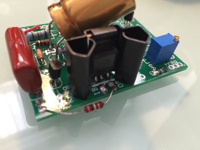
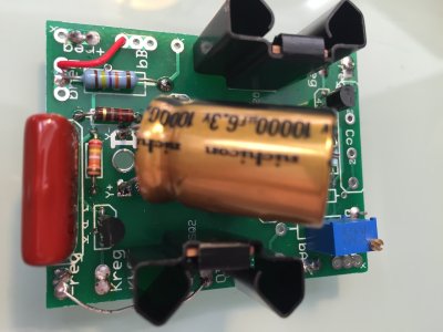
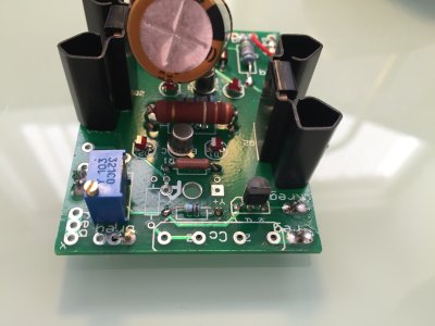
Power Supply Board Manual Paramount 1 Paramount 2

6V-Red Wire 3.1VAC 0 0
6V-Black Wire 3.1VAC 0 0

C4S/soft Start Board Manual Paramount 1 Paramount 2

Kreg (A Side) 4.1 1.88 measured on 20v setting 1.87 measured on 20v setting
Kreg (B Side) 6.3 3.96 measured on 20v setting 4.79 measured on 20v setting
OA 300 146 149.5
OB 175 143.4 147.8

Trimmer Screw Adj. Paramount 1 Paramount 2

300k Resistor OB end 143.4 147.8

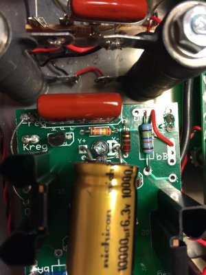
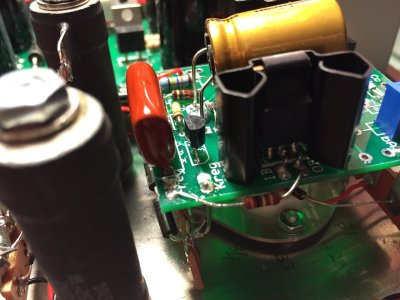
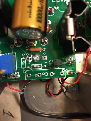
The power supply board values are making me suspect that something has gone wrong in that area however T11, T12, T19, T20, B3, B6 all see a little off.

Voltage wise the Power Supply Board is clearly not right and the Soft Start Board is low across the board...

Any help would be much appreciated - given the consistency across the two units it feels like I have made a schoolboy error in the same place on both of them!

Thanks,

Bill
 
The only power supply voltage you quote is the 6.3v winding, which must be measured on the AC volts scale, not DC volts. Since the tube lights up, it is getting the desired voltage.

The low voltage on the driver board are confusing me - would you first make sure you have identified the measurements with the correct (A or B) side, and if so re-check that the A and B sides are wired correctly, both on the board and from board to circuit?

The reason for the above is that the low kreg voltage would make more sense to me if it were on the other side.
 
Thanks Paul, all help much appreciated...

1) Schoolboy error on the measurement of the AC volts - proper measurements below.

2) Re-soldered all main joints, took off the driver board and re-attached...

3) I believe I have the correct A and B side - slightly different figures this time for Kreg A

Updated measurements:

Resistance

Terminal Manual Paramount 1

1 * *
2 No Connection No connection
3 No Connection No Connection
4 No Connection No Connection
5 1K 1K
6 1118 1118
7 249k 248K
8 No Connection No connection
9 124k * *
10 0 0
11 3.0M Infinity
12 5.6M Infinity
13 0 0
14 9.2M Infinity
15 15M Infinity
16 * *
17 0 0
18 0 0
19 128k 177k Measured on the 20k setting
20 249k 2.47k on 20k setting

Four Pin Socket Manual Paramount 1

A1 1027 1029
A2 * Infinity
A3 249K 248k
A4 1028 1030

Nine Pin Socket Manual Paramount 1

B1 0 0
B2 8.2k 14.9k
B3 249k 2.71k on 20k setting
B4 130k * 268k
B5 0 0
B6 177k * 363 measured on 2000k setting
B7 220 236
B8 * infinity
B9 * 0

Voltage 240V 300B

Line Voltage 243.7


Terminal Manual Paramount 1

1 440 446
5 71 74
9 175 145.8
10 0 0

16 457 472
17 0 0
18 0 0
19 175 145

Four Pin Socket Manual Paramount 1

A1 74.1 78
A2 440 441
A3 Close to 0 2.9 measured on 20v setting
A4 69.2 73

Power Supply Board

Terminal Manual Paramount 1

6V-Red Wire 3.1VAC 2.8VAC
6V-Black Wire 3.1VAC 2.8VAC

C4S/soft Start Board

Terminal Manual Paramount 1

Kreg (A Side) 4.1 4.76 on 20v setting
Kreg (B Side) 6.3 1.86 on 20v setting
OA 300 150
OB 175 146

Trimmer Screw Adj.

300k Resistor OB end 143.4

Tube EH 300b

I have attached pictures of the driver board and the 9 pin socket underneath. For reference I am measuring kregB from the kreg label in the bottom left of image 'Driver Board 1' and kregA to the immediate right of the heatsink in the top right of the image.

kregB connecting to B8

OB connecting to B4

-kreg (A side) connecting to T17U

IA connecting to T16U

Kreg (A side) to B2

OA to B6


Many thanks,

Bill
 

Attachments

  • Driver Board 1.jpg
    Driver Board 1.jpg
    293.1 KB · Views: 121
  • Driver Board 2.jpg
    Driver Board 2.jpg
    252.5 KB · Views: 111
  • Driver Board 3.jpg
    Driver Board 3.jpg
    228.2 KB · Views: 109
  • Driver Board Underside.jpg
    Driver Board Underside.jpg
    217.7 KB · Views: 115
  • Terminal 11 15.jpg
    Terminal 11 15.jpg
    259.1 KB · Views: 119
Nice, careful documentation - it's a big help, thanks!

Assuming that swapping the 5670 made no difference, here's what I see so far:

The low voltage at OA indicates the regulator output is far too low, and the low voltage at kreg on the B side indicates that's because the 431 is saturated.

I can't get a good look at the B side 431 and its associated R3 (2.49K). From the back side I can't see that there is anything in the 431 holes at all, but it may be just a trick of the light. Anyhow that 431 and associated 2.49K R3 are the places I'd look first. If the R3 is not connected, or the wrong value. If you put the 4.99K resistor in there (instead of in the A side R3, where it belongs) you would get a regulated voltage of 150v, which is what you have - but I'm not ruling out coincidence yet!
 
Paul, thanks for the help... I think the resistors are in the correct holes... I have attached a few more pictures to show those areas of the board more clearly. I will re-do the solder joints in the morning (taking snaps of the front and back) and will check the 5670 at the same time. I am currently waiting on more solder being delivered - what a time to run out!!!

Thanks,

Bill
 

Attachments

  • B Side 431 - b.jpg
    B Side 431 - b.jpg
    207.4 KB · Views: 105
  • B Side 431 - a.jpg
    B Side 431 - a.jpg
    277.9 KB · Views: 117
  • A Side 431 - b.jpg
    A Side 431 - b.jpg
    203.3 KB · Views: 109
  • A Side 431 - a.jpg
    A Side 431 - a.jpg
    302.6 KB · Views: 109
Ok, solder arrived so I have taken off the driver board, heated every solder point on the back, touched up any on the top that looked like it could do with some more contact. Reattached and got exactly the same readings as before.

Assume this rules out any issue with a specific 5670 as the same issue is showing on both...

I hooked up my second Paramount and it is giving essentially the same readings... Readings listed again for completeness... Along with some more pics of the driver board prior to me reattaching it...

Resistance

Terminal Manual Paramount 1 Paramount 2

1 * * Infinity
2 No Connection No connection No connection
3 No Connection No Connection No connection
4 No Connection No Connection No connection
5 1K 1K 1k
6 1118 1118 1118
7 249k 248K 248
8 No Connection No connection No connection
9 124k * * *
10 0 0 0
11 3.0M Infinity 889k
12 5.6M Infinity 1825k
13 0 0 0
14 9.2M Infinity Infinity
15 15M Infinity Infinity
16 * * *
17 0 0 0
18 0 0 0
19 128k 177k Measured on the 20k setting 177.7 Measured on the 200k setting
20 249k 2.47k on 20k setting 2.47k on 20k setting

Four Pin Socket Manual Paramount 1 Paramount 2

A1 1027 1029 1023
A2 * Infinity Infinity
A3 249K 248k 248k
A4 1028 1030 1016

Nine Pin Socket Manual Paramount 1 Paramount 2

B1 0 0 0
B2 8.2k 14.9k 14.96k
B3 249k 2.71k on 20k setting 2.71k on 20k setting
B4 130k * 268k 130k
B5 0 0 0
B6 177k * 363 measured on 2000k setting 364 measured on 2000k setting
B7 220 236 228
B8 * infinity Infinity
B9 * 0 0

Voltage 240V 300B

Line Voltage 246.3


Terminal Manual Paramount 1 Paramount 2

1 440 446 440
5 71 74 74
9 175 145.8 148
10 0 0 0

16 457 472 465
17 0 0 0
18 0 0 0
19 175 145 148

Four Pin Socket Manual Paramount 1 Paramount 2

A1 74.1 78 77
A2 440 441 440
A3 Close to 0 2.9 measured on 20v setting 6 measured on 2000m setting
A4 69.2 73 72.8

Power Supply Board

6V-Red Wire 3.1VAC 2.8 2.7
6V-Black Wire 3.1VAC 2.8 2.7

C4S/soft Start Board

Kreg (A Side) 4.1 4.81 on 20v setting 3.98 measured on 20v setting
Kreg (B Side) 6.3 1.85 on 20v setting 1.84 measured on 20v setting
OA 300 148.3 142.5
OB 175 146 144.2

Trimmer Screw Adj.

300k Resistor OB end 143.4 142.5

Tube EH 300b
 

Attachments

  • Driver1.jpg
    Driver1.jpg
    208.6 KB · Views: 111
  • Driver2.jpg
    Driver2.jpg
    244.9 KB · Views: 109
  • Driver3.jpg
    Driver3.jpg
    238.3 KB · Views: 104
  • Driver4.jpg
    Driver4.jpg
    224.3 KB · Views: 96
  • Driver5.jpg
    Driver5.jpg
    180.4 KB · Views: 97
  • Driver6.jpg
    Driver6.jpg
    133.1 KB · Views: 100
  • Driver7.jpg
    Driver7.jpg
    122.8 KB · Views: 98
I see 249K resistors on the board where 2.49K resistors should be.  Check your color codes and parts between amps. 

-PB
 
Ah ha! I think that may well be it - soldering iron is warming up as I type!!!

Fingers crossed...

Thanks,

Bill
 
PB, I think you nailed it... Fixed one Paramount and readings are now spot on... Doing the second while the first sits for 20 mins before trying with music... Fingers crossed!!!
 
PB - you were bang on with your prognosis... Resistors swapped and Paramounts starting to sing! Cant believe I didn't notice it - especially looking back on the resistance check...

Thanks again - very much appreciated, as was the help from Paul!!!

Bill
 
That was exactly the reason I kept asking for pictures that showed that resistor and the associated 431.

So, the 431 was saturated and the 150 volts being half of the target 300 volts was just a coincidence.

Re "... I think the resistors are in the correct holes..." - yeah we've all been there; I get reflexively suspicious whenever I hear myself saying that. Which I do, all too often! When in doubt, check. Still in doubt, check again. Absolutely certain, get someone else to check for you.
 
I think I was thrown by how much it looked like the part in the photograph in the manual when I should really have been trusting the meter / re-reading the text and thinking about the words...

Thanks again for all your help - the end result is nothing short of spectacular!!!
 
Congratulations!

I too have messed up on the resistors on the pcb....you're not alone!  I hopefully will be fixing them this week.

Enjoy your sweet music.  Anxiously waiting to hear mine!...


Back
Top