Smash build with a few wonky resistance measurements (resolved)

FS

New member
Hello,

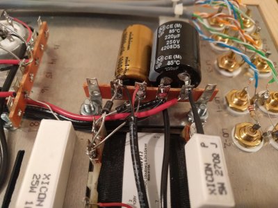
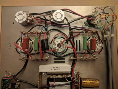
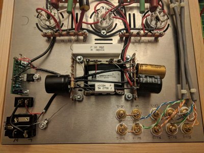
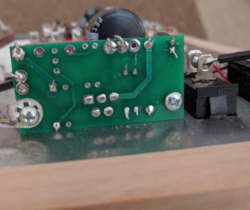
I have built the Smash in the stock version. Most of the resistance values were spot on. All the terminals with an asterisk (*) in the resistance check showed as OL on my meter. However, terminal 26 should be * but shows 0 Ohms. Terminal 31 on the other hand should be 0 Ohms, but gives an OL reading. Terminal 35 should be *, and showed up as OL in one reading, but then as 0.04 and slowly rising in another one. I tried to redo the soldering on the wires and components and re-flowed solder at the PT side for some terminals, but repeat measurements gave me the same readings. This can't be just a grounding problem, but I have painted the chassis and PT). The screws are tight. Thanks in advance for your help with troubleshooting. Cheers, FS 
 
26 being 0 ohms means that the shielded twisted pair wires going from those terminals to the PC board, then to the sockets has an error.  For some reason, it is extremely common for builders to switch a black wire and a shield wire along the way, and this will ground out the negative end of the filament supply.

For terminal 31, just tighten up the hardware on the power transformer a bit.  If the tightening doesn't help, you can carefully remove the screw on that corner and scrape off a little paint under where it rests against the power transformer cover.
 
I had a similar problem on terminal 31. I took a Dremel with a grinder bit to it and it cleared things up.
 
Hi PB and Oguinn,
I have taken out the screws and sanded underneath the bell end and the top of the core. After re-assembly, terminals 25, 30, 31, and 36 are now properly grounded. I have checked the shielded twisted pair cable, and it connects all the right terminals. Colors are not switched. What should I read at the PC board? I have some troubles at terminal 26, had to re-solder a few times and it is still not OL, it reads 360 Ohms now, terminal 27 is OL.
Cheers,
FS
 
Is it 360 ohms, or 360k ohms? If it’s in the tens or hundreds of thousands of ohms it should be ok according to the manual.
 
Terminal 26 shows a resistance reading of 360 Ohms when set to the 2K range. Terminal 27 shows a a high resistance reading going up until it hits OL. Terminal 26 is the only one that shows a deviation from the resistance values published in the manual on page 47. As I had said, the shielded twisted pair cable to the filament regulatory board (as described on pages 35 and 36) shows all connections made properly, with the red wire going to terminal 27U and the black wire going to 26U. The other end that goes to the PC board has the drain wire attached to the solder tab. The red wire goes to the "In" solder pad, the black to the "GND" solder pad. Resistance reading at the "GND" pad show 360 Ohms on the black wire end, OL on the tab. Resistance reading on the "In" pad are OL, and a high resistance creeping up to OL on the red wire end that is connected to it, which are the same values as on terminals 26 and 27 on the other side of the cable.
I have checked that the UF4007 rectifier diodes and the 5818 Schottky diodes are in the correct orientation and don't touch other pads, terminals or wires.
 
It’d probably help Paul and the Bottlehead guys if you posted pictures of your build. Paul has a pretty keen eye for catching issues.

I’m also a novice with this stuff, so I’ve exhausted my usefulness.
 
Here are a few pics of the Smash build...
 

Attachments

  • IMG_20190217_124511.jpg
    IMG_20190217_124511.jpg
    813.9 KB · Views: 11
  • IMG_20190217_124448.jpg
    IMG_20190217_124448.jpg
    512 KB · Views: 11
  • IMG_20190217_124528.jpg
    IMG_20190217_124528.jpg
    601.5 KB · Views: 11
  • IMG_20190217_124545.jpg
    IMG_20190217_124545.jpg
    661.5 KB · Views: 13
Hi Paul,

I have attached a few more pics, including a close-up of the back of the PC board.
 

Attachments

  • IMG_20190213_000929.jpg
    IMG_20190213_000929.jpg
    571.2 KB · Views: 9
  • IMG_20190213_000912.jpg
    IMG_20190213_000912.jpg
    617 KB · Views: 4
  • IMG_20190213_000902.jpg
    IMG_20190213_000902.jpg
    577.8 KB · Views: 4
  • IMG_20190213_000846.jpg
    IMG_20190213_000846.jpg
    598.4 KB · Views: 3
  • IMG_20190213_000646.jpg
    IMG_20190213_000646.jpg
    660.6 KB · Views: 7
  • IMG_20190213_000634.jpg
    IMG_20190213_000634.jpg
    676.6 KB · Views: 13
  • IMG_20190217_150036.jpg
    IMG_20190217_150036.jpg
    273.9 KB · Views: 13
FS said:
Resistance reading at the "GND" pad show 360 Ohms on the black wire end, OL on the tab.
OL at the ground tab on the PC board?  The ground tab is grounded to the chassis.  If you see "OL" there, then your chassis isn't grounded. This is a contradiction since 6U touches the chassis and the grounding lug touches the chassis.  You are using 6U as your ground reference correct?

There is 360 ohms (approximately) of resistance between "OUT" and "GND" on the PC board, can you verify this measurement? 
 
I am using 6U as the reference. Checking these measurements again, I get 360 Ohms at 26, A1, and C1, OL at 27, 360 at the "GND" of the PC board, OL at the "In" of the PCB.  And yes, I confirm that there is 360 Ohms between "GND" and "OUT" of the PCB.
6U shows as grounded - I measured 0 Ohms against other grounded terminals.
 
I have unscrewed the PCB and the L-200 from the chassis. lifted them up to make sure there is no contact. I remeasured and got the following resistance values:
0 at terminal 25, OL at 26, OL at 27, 0 at 28, OL at 29, 0 at 30.
On the PCB, I got OL on the soldering tab, IN, GND, and OUT.
 
Yeah, so I'd review the mounting instructions for the heatsink mounting kit.  The metal tab of the L-200 was touching the chassis and causing these issues.  This can happen if the shoulder washer isn't properly installed onto the metal tab of the L200, or if the mica insulator is well out of position.
 
When I removed the PCB from the chassis, the mica insulator pad looked well positioned to prevent the L-200 touching the chassis. I have reinstalled this, with the mica covering the full length and width of the L-200 metal tab. The shoulder washer is properly set.
I still have the same issue. The screw and the nut show OL, the L-200 tab shows 360 Ohms. Shall I insulate the mica from the cassis with electrical tape underneath, and another piece of electrical tape over the shoulder washer?
 
Pull it back off an check again.

I'll reiterate that the solder tab, screws, and L-bracket touch the chassis, and terminal 6 touches the chassis, ergo the solder tab should show 0 ohms.  Do the L-brackets themselves show 0 ohms?  What is the DC resistance between the L-200 metal tab and the chassis when it's mounted?

 
Pulled it off and mounted it again. The mica sits perfectly under the L-200 body, and the shoulder washer is properly set. The screw and nut holding the L-200 showed OL at first, so I tightened them to make proper contact. It not shows a reading of 0 Ohms. The resistance between the L-200 when mounted and the chassis is 360 Ohms. The solder tab at the PCB shows 0 Ohms. The L-brackets also show 0 Ohms against ground/chassis.

 
Let's see some closeup photos of the L-200 where it's mounted.  The metal tab of the L-200 is internally connected to the ground reference of the regulator (the solid black wires coming in and out of the board).  If these measure properly when the L-200 isn't mounted to the chassis, then we have to conclude that there's something weird going on with the mounting. 

-PB
 
In the last pic you posted of the back of the Reg board, is the solder connection at the lower left,  closest to the screw perhaps touching the top plate?...John
 
Back
Top